Proximity sensors are essential components in industrial automation, providing non-contact detection of metallic or non-metallic objects. Proper wiring is critical to ensure reliable operation, safety, and longevity of these sensors. This tutorial covers the fundamental wiring principles for both DC and AC proximity sensors, common configurations, and practical tips for installation.
First, identify the sensor type: two-wire, three-wire, or four-wire. Two-wire sensors are simple, connecting in series with the load, but they may have higher leakage current. Three-wire sensors are most common, with separate wires for power, ground, and output. Four-wire sensors typically include two output channels (e.g., NO and NC).
For DC three-wire sensors:
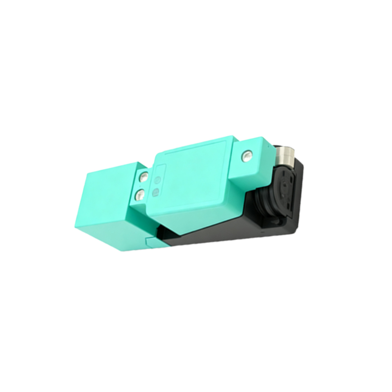
- Brown wire: Connect to DC positive (+).
- Blue wire: Connect to DC negative (-) or ground.
- Black wire: Output signal; connect to the load (e.g., PLC input).
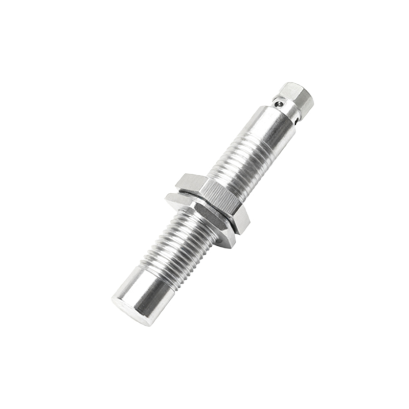
Ensure the power supply voltage matches the sensor rating (typically 10-30 VDC). Use shielded cables in electrically noisy environments, grounding the shield at one end.
For AC three-wire sensors:
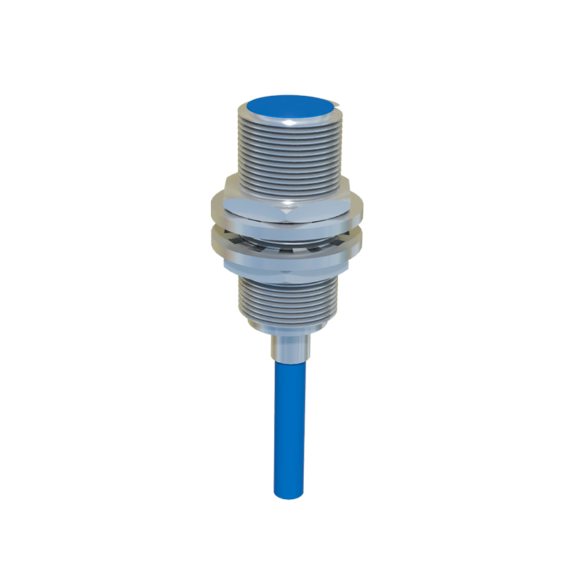
- Brown wire: Connect to AC line (L).
- Blue wire: Connect to AC neutral (N).
- Black wire: Output signal; connect to the load.
Verify the voltage rating (e.g., 90-250 VAC) and frequency compatibility. Include a separate ground wire if provided.
Wiring steps:
1. Power off the circuit and lock out/tag out (LOTO) for safety.
2. Strip wires to the appropriate length (refer to sensor datasheet).
3. Use crimp terminals or direct wiring, ensuring secure connections.
4. Route cables away from high-voltage lines and motors to avoid interference.
5. Test with a multimeter: check voltage at the sensor and output switching.
Common configurations:
- Sinking (NPN) output: The output switches the negative side; common in Europe and Asia.
- Sourcing (PNP) output: The output switches the positive side; common in North America.
Confirm the PLC input compatibility (sinking vs. sourcing) before wiring.
For two-wire AC/DC sensors, connect in series with the load. Note that the residual current when off may affect sensitive loads. Four-wire sensors allow independent NO/NC outputs; wire according to the required logic.
Installation tips:
- Maintain the sensing distance specified in the manual.
- Avoid mounting multiple sensors too close to prevent mutual interference.
- Use conduit or cable glands in harsh environments (dust, moisture).
- Regularly inspect for loose connections or cable damage.
Troubleshooting:
- No output: Check power supply, wiring polarity, and load compatibility.
- Intermittent operation: Look for vibration, noise, or shielding issues.
- False triggers: Ensure no metal objects are within the sensing range.
Always consult the manufacturer’s datasheet for specific details, as wire colors and functions may vary. Proper wiring not only enhances performance but also reduces downtime and maintenance costs in industrial systems.