Proximity sensors are indispensable components in modern industrial automation, serving critical roles in object detection, positioning, and counting without physical contact. Proper calibration and debugging are paramount to ensure their reliability, accuracy, and longevity within a control system. This guide provides a systematic, engineer-oriented approach to proximity sensor setup and troubleshooting, supplemented with clear diagrammatic references.
Understanding the Fundamentals and Pre-Calibration Checklist
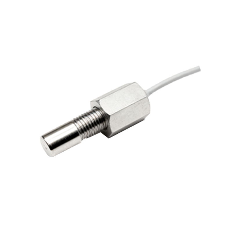
Before initiating any calibration procedure, a thorough understanding of the sensor type is essential. The two primary categories are inductive (for detecting metallic objects) and capacitive (for detecting both metallic and non-metallic objects). Always consult the manufacturer's datasheet for specific parameters such as sensing distance (Sn), hysteresis, output type (PNP/NPN, NO/NC), and supply voltage requirements.
Pre-Calibration Checklist:
1. Power Safety: Ensure all power to the circuit and machinery is locked out and tagged out (LOTO) before wiring.
2. Mechanical Mounting: Verify the sensor is securely mounted, free from vibration, and aligned correctly with the target's path of travel. Refer to Diagram A for standard mounting clearances, which illustrate the necessary space between the sensor face and surrounding metal to prevent false triggering.
3. Wiring Verification: Confirm wiring against the datasheet. A typical 3-wire DC sensor requires Brown (+V), Blue (0V/Common), and Black (Output). For a PNP sensor, the load is connected between the Black wire and Blue wire. Incorrect wiring is a leading cause of failure.
4. Target Specification: Confirm the target material, size, and shape. The standard sensing distance (Sn) is defined for a mild steel target of a specific size. For other materials, a correction factor must be applied (e.g., stainless steel may reduce the effective sensing distance).
Step-by-Step Calibration & Adjustment Procedure
The goal of calibration is to set the sensor's operating point within its reliable range, accounting for real-world variables like target positioning and environmental conditions.
1. Initial Power-Up: Apply the correct voltage. A stable power supply is critical; voltage spikes or drops can cause erratic behavior. Observe the sensor's indicator LED (usually a red or green light).
2. Distance Adjustment: The core adjustment involves the distance between the sensor face and the target. The effective operating distance should be set to 50-80% of the rated sensing distance (Sn) to account for mechanical tolerances, thermal drift, and voltage fluctuations. Diagram B demonstrates this principle, showing the optimal operating zone well within the nominal range, avoiding the unstable edges.
3. Potentiometer Adjustment (if equipped): Many sensors feature a potentiometer for sensitivity adjustment.
Inductive Sensors: Turn the pot clockwise to increase sensitivity (increase sensing distance). Introduce the standard target and adjust until the output reliably triggers. Then, decrease sensitivity slightly to provide a safety margin against false triggers from environmental metal or vibration.
Capacitive Sensors: These are sensitive to material density and moisture. Adjust the pot with the target present until activation occurs. Then, introduce the background material (e.g., the container wall) and adjust counter-clockwise to desensitize the sensor, preventing background interference. Diagram C contrasts the adjustment focus for inductive versus capacitive types.
4. Response Time & Hysteresis: For high-speed applications, verify the sensor's response time meets the cycle requirement. Hysteresis—the difference between the switch-on and switch-off points—is a built-in feature to prevent chatter. Understand this value from the datasheet; it is not typically adjustable.
Systematic Troubleshooting Methodology
When a proximity sensor malfunctions, a logical diagnostic approach is required.
Symptom: No Output (Indicator LED OFF).
Diagnosis: Check power supply voltage at the sensor terminals with a multimeter. Verify wiring for breaks or loose connections. Ensure the load (e.g., PLC input, relay) is not short-circuited.
Symptom: No Output (Indicator LED ON).
Diagnosis: This indicates the sensor detects the target but the signal is not reaching the controller. Check the output wiring from the sensor to the load. Test the load by temporarily substituting a known-good sensor. The issue may be a faulty PLC input module or broken wire.
Symptom: Constant Output (Indicator LED ON, no target present).
Diagnosis: For inductive sensors, this is often caused by metal debris on the sensing face or a nearby metal object within the sensing field (see Diagram A for clearance violations). For capacitive sensors, environmental changes like humidity, dust buildup, or a change in the background material can cause