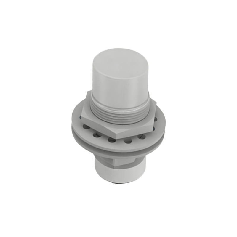
Proximity sensors are indispensable components in modern automation, robotics, and safety systems. They detect the presence or absence of an object without physical contact, using various principles such as inductive, capacitive, ultrasonic, or optical methods. For engineers and hobbyists looking to understand the underlying technology or create a custom solution, building a basic proximity sensor can be an enlightening project. This guide outlines a method to construct a simple inductive proximity sensor, commonly used for detecting metallic objects.
The core principle of an inductive proximity sensor involves generating an electromagnetic field using a coil. When a metallic object enters this field, eddy currents are induced in the object, which in turn alter the oscillation characteristics of the coil's circuit. This change is detected and converted into a usable output signal, typically a digital high/low or an analog voltage.
To begin construction, you will need several key components: an oscillator circuit (often built around a 555 timer IC or a dedicated oscillator coil), a detection circuit (such as a Schmitt trigger or comparator like the LM393), a coil (usually wound from enameled copper wire), a power supply (commonly 5V or 12V DC), resistors, capacitors, and an output indicator like an LED or a relay. A printed circuit board (PCB) is recommended for stability, though a breadboard can suffice for prototyping.
Start by designing the oscillator. Using a 555 timer in astable mode is a straightforward approach. Connect the timer IC with appropriate resistors and a capacitor to generate a high-frequency signal, typically between 100 kHz and 1 MHz. The coil, acting as an inductor, is placed in the feedback loop of the oscillator. Wind the coil carefully; for a typical range of a few millimeters, use about 50-100 turns of 0.2-0.5 mm diameter enameled wire around a ferrite core to enhance sensitivity. Secure the coil and connect it to the oscillator circuit.
Next, implement the detection stage. As a metal object approaches the coil, the oscillation amplitude dampens. This change can be captured by a peak detector circuit (a diode and capacitor) to convert it into a DC voltage. Feed this voltage into a comparator, such as the LM393, set with a reference voltage via a potentiometer to adjust the sensing threshold. When the detected voltage drops below the threshold (indicating proximity), the comparator output switches state.
For the output, connect the comparator's output to an LED with a current-limiting resistor for visual feedback, or to a transistor driving a relay for switching higher loads. Ensure proper decoupling capacitors are placed near IC power pins to minimize noise, which is crucial for stable operation. Enclose the sensor in a non-metallic housing, leaving only the coil face exposed, to shield it from environmental interference and mechanical damage.
Testing and calibration are critical. Power the circuit and use a metallic object, such as a screw or a coin, to verify detection. Adjust the potentiometer to set the desired sensing distance. Note that factors like object size, material (ferrous vs. non-ferrous metals), and external electromagnetic noise can affect performance. For industrial applications, additional shielding, temperature compensation, and signal conditioning may be necessary.
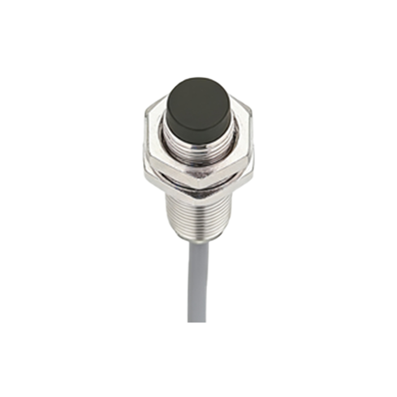
Building a proximity sensor from scratch provides deep insight into electromagnetic theory and circuit design. While commercial sensors offer refined features like extended ranges, IP ratings, and various output formats, this hands-on project enhances practical engineering skills. It underscores the importance of precision in component selection, layout, and calibration. For further exploration, consider experimenting with capacitive sensors for non-metallic objects or integrating microcontroller-based signal processing for smart detection capabilities.