In modern industrial automation, achieving precise and reliable material handling, robotic guidance, and autonomous vehicle navigation is paramount. The laser sensor line following process stands as a cornerstone technology for these applications, offering superior accuracy, robustness, and adaptability compared to traditional methods. This guide details the systematic workflow, key considerations, and best practices for implementing an effective laser-based line following system.
The core principle involves a laser sensor, typically a time-of-flight or triangulation-based device, emitting a focused beam onto a target surface. A contrasting guide line, often a high-reflectivity tape or a painted strip against a low-reflectivity background (or vice versa), is applied to the floor or work surface. The sensor's receiver detects the reflected light intensity. The fundamental operation hinges on the significant difference in reflected intensity between the line and the background. The sensor's onboard processor converts this analog intensity signal into a digital reading. By continuously scanning or taking discrete measurements perpendicular to the direction of travel, the system determines the lateral position of the line relative to the sensor's centerline.
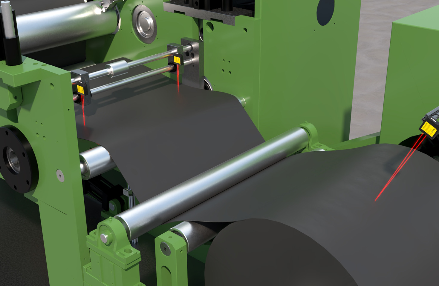
The implementation process follows a structured sequence. First, a thorough System Assessment and Line Specification is conducted. This involves analyzing the operational environment—factors like ambient light conditions, floor material, potential contaminants (oil, dust), and required traversal speed. The guide line's width, color, and material are selected to maximize contrast. For instance, a retro-reflective tape is highly effective in variable lighting. Concurrently, a suitable laser sensor is chosen based on scanning range, response time, resolution, and environmental protection ratings (e.g., IP67).
Next is Sensor Installation and Calibration. The sensor is mounted on the mobile platform—an AGV, robot, or conveyor cart—at an optimal height and angle to ensure the laser spot is correctly focused on the surface. Calibration is a critical step. The sensor is positioned over the background and then over the line to teach it the minimum and maximum reflection values. This establishes the threshold for line detection. Advanced sensors allow for dynamic threshold adjustment to compensate for gradual environmental changes.
The heart of the process is the Data Acquisition and Position Calculation. As the platform moves, the sensor samples the reflected intensity at a high frequency (often in the kHz range). The output is typically a digital value or an analog voltage/current proportional to the detected light level. A Programmable Logic Controller (PLC) or a dedicated motion controller receives this data. Using a predefined algorithm, commonly a Proportional-Integral-Derivative (PID) control loop, the controller calculates the error signal—the deviation of the detected line center from the sensor's reference center.
This error signal drives the Guidance and Motion Control phase. The PID algorithm outputs a correction command. For a differential-drive vehicle, this translates into adjusting the speed of the left and right wheels. If the line drifts to the left, the right wheel may slow down or the left wheel may speed up to steer the platform back to center. For conveyor-based systems, it might adjust the angle of guiding rollers. The system's responsiveness and stability depend heavily on fine-tuning the PID constants (Kp, Ki, Kd) to match the platform's dynamics and speed.
Path Navigation and Decision Logic handles intersections, curves, and stops. For complex paths with branches or 90-degree turns, multiple sensors in an array or a single scanning sensor are used. The controller is programmed with logic to interpret specific patterns. For example, a sudden loss of signal might indicate an intersection; the system then refers to its programmed route to decide whether to turn left, right, or continue straight, often triggered by a secondary marker or an encoded instruction. Sharp curves require predictive adjustments, sometimes aided by look-ahead algorithms that use the rate of change of the error signal.
Finally, System Integration and Validation ensures robustness. The line following module is integrated with higher-level systems like Warehouse Management Systems (WMS) or Manufacturing Execution Systems (MES). Comprehensive testing under real-world conditions—different lighting, partial line obscuration, surface irregularities—is performed. Diagnostics for line break detection and recovery procedures (e.g., stop, reverse, search pattern) are implemented to ensure operational safety and uptime.
Key advantages of laser-based line following include immunity to ambient color changes (unlike vision cameras), high precision (often sub-millimeter), and excellent performance in dusty or mildly dirty environments. However, challenges such as highly specular (shiny) floors or complete obscuration of the line require mitigation strategies like sensor fusion or using physical guide walls at critical sections.
In conclusion, a meticulously planned laser sensor line following process, from precise line specification and sensor calibration to sophisticated motion control and fault handling, forms a reliable backbone for automated guidance. Its success hinges on a deep understanding of both the sensor technology and the mechanical dynamics of the guided platform, ensuring seamless, efficient, and uninterrupted material flow in smart factories and logistics centers.