Replacing a laser sensor in an industrial setting is a critical maintenance task that ensures precision measurement, alignment, and control systems function reliably. Whether due to aging, physical damage, or calibration drift, a faulty laser sensor can disrupt production lines and compromise quality. This guide provides a systematic, safety-focused approach for engineers and technicians to replace laser sensors effectively.
Before starting, gather necessary tools: insulated screwdrivers, multimeter, appropriate replacement sensor (verify model compatibility), cleaning supplies, and personal protective equipment (PPE) like safety glasses. Always consult the sensor’s manual and system schematics.
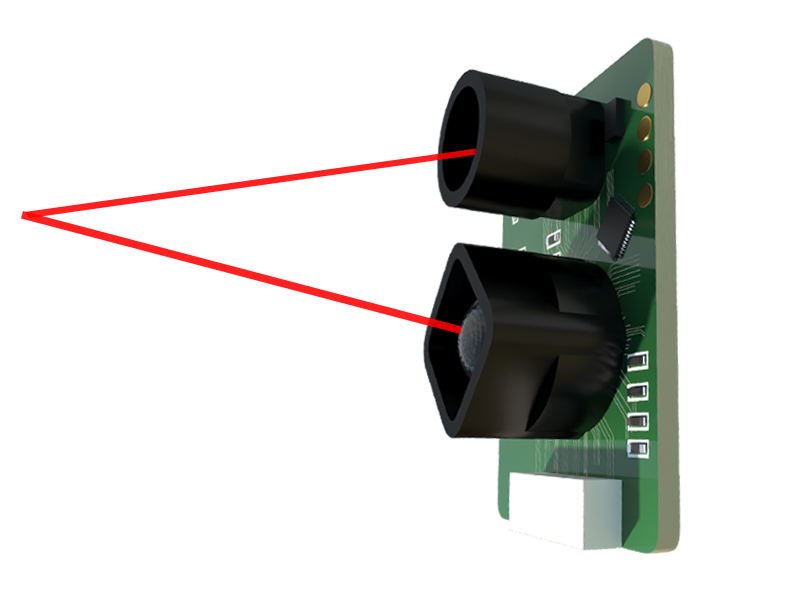
Step 1: Power Down and Lockout/Tagout
Ensure complete electrical isolation. Follow lockout/tagout (LOTO) procedures to disconnect power to the sensor and associated machinery. Verify zero energy state using a multimeter. This prevents electrical shock and accidental activation.
Step 2: Document Connections and Settings
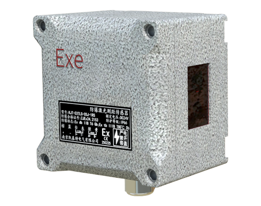
Label all cables and connectors with tags or photos. Record configuration parameters (e.g., sensing range, output type, teach-in points) from the old sensor’s controller interface or dip switches. This data is vital for reprogramming the new unit.
Step 3: Remove the Old Sensor
Carefully disconnect cables, noting their orientation. Unscrew mounting hardware, avoiding force that could damage brackets or conduits. Inspect the mounting surface for corrosion or misalignment; clean if necessary.
Step 4: Install the New Sensor
Mount the replacement sensor securely, ensuring it is level and aligned per specifications. Reconnect cables precisely as documented. Avoid overtightening connections, which may cause signal interference or physical damage.
Step 5: Power Up and Configure
Restore power gradually. Input recorded settings into the new sensor via its interface or software. Many modern laser sensors feature auto-configuration tools; use these if available, but verify parameters manually.
Step 6: Calibrate and Test
Perform calibration according to manufacturer guidelines. Use a test target to check sensing accuracy and repeatability. Monitor output signals (e.g., analog voltage, digital pulses) with a multimeter or oscilloscope. Run the system through operational cycles to ensure integration with PLCs or controllers is seamless.
Step 7: Validate System Performance
Observe the sensor under normal operating conditions for at least one production cycle. Check for environmental factors like vibration, temperature shifts, or ambient light that could affect performance. Document the replacement in maintenance logs, including sensor serial number and calibration date.
Common Pitfalls to Avoid
- Using incompatible sensors: Even similar-looking models may have different output protocols or power requirements.
- Skipping calibration: This leads to measurement errors and potential system faults.
- Neglecting environmental seals: In dusty or humid areas, ensure IP-rated enclosures are properly sealed.
Regular maintenance, such as lens cleaning and periodic recalibration, extends sensor lifespan. If issues persist post-replacement, review wiring integrity and controller programming.
By following these steps, maintenance teams can minimize downtime and ensure laser sensors operate with optimal accuracy, supporting efficient and safe industrial automation.