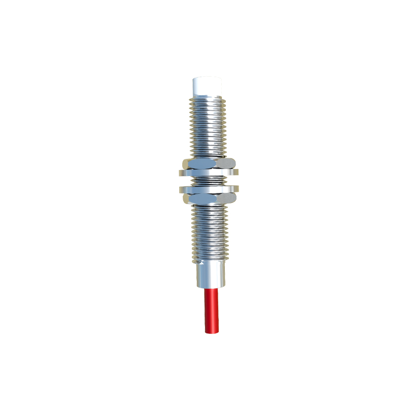
Magnetic proximity sensors are essential components in modern industrial automation, offering non-contact detection of ferromagnetic objects. These sensors rely on the Hall effect or magnetoresistive principles to generate electrical signals when exposed to magnetic fields. Understanding the circuit diagram of a magnetic proximity sensor is crucial for engineers to ensure proper integration, troubleshooting, and optimization in systems such as conveyor belts, robotic arms, and safety interlocks.
A typical magnetic proximity sensor circuit consists of several key sections: the sensing element, signal conditioning circuitry, output stage, and power supply regulation. The core sensing element is often a Hall-effect IC or a magnetoresistive chip. When a magnet or ferrous object enters the sensor’s detection range, the magnetic field alters the charge carrier movement in the semiconductor material, producing a small voltage differential. This微弱 signal is then fed into an operational amplifier (op-amp) stage for amplification and noise filtering. The op-amp circuit, usually configured with precision resistors and capacitors, boosts the signal to a usable level while suppressing electromagnetic interference common in industrial environments.
Following amplification, the conditioned signal passes through a comparator circuit. This stage compares the sensor signal against a predefined threshold voltage, set by a voltage divider network. Once the signal exceeds the threshold, the comparator switches its output state, triggering the output stage. The output configuration varies based on sensor type: common versions include NPN open-collector, PNP open-emitter, or push-pull outputs. These interfaces connect to programmable logic controllers (PLCs) or relay modules. For instance, an NPN output circuit involves a transistor that sinks current to ground when activated, signaling a detected object. Protection components like flyback diodes or transient voltage suppressors are integrated to guard against voltage spikes from inductive loads.
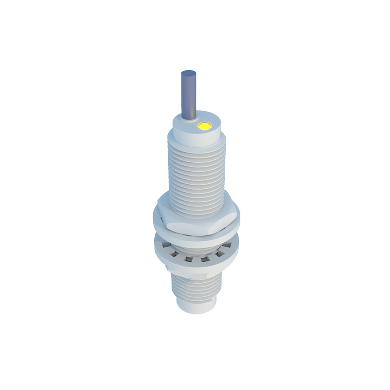
Power management is another critical aspect. Industrial sensors typically operate on 10-30V DC supplies. A voltage regulator IC, such as a 78L05, provides stable 5V or 3.3V to the sensitive analog and digital components. Decoupling capacitors are placed near IC power pins to minimize ripple and ensure reliable operation. Additionally, many circuits include diagnostic features like LED indicators driven by transistor buffers, which visually signal power-on status and detection events without loading the main circuit.
When designing or analyzing such circuits, engineers must consider factors like sensing distance, hysteresis, and response time. Hysteresis, implemented via positive feedback in the comparator, prevents output oscillation when the target object is near the detection threshold. Environmental robustness is achieved by conformal coating on the PCB and using temperature-stable components, as industrial settings may involve moisture, vibrations, or extreme temperatures.
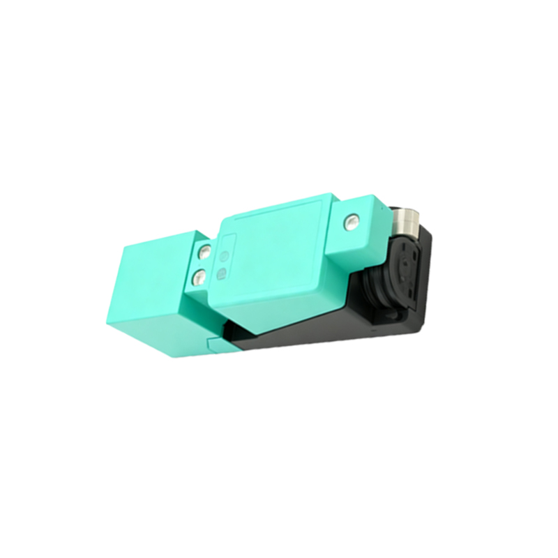
In summary, the magnetic proximity sensor circuit transforms subtle magnetic field changes into robust digital signals. Mastery of its schematic enables customization for specific applications, such as adjusting sensitivity via potentiometers or adding analog output options for continuous position sensing. As Industry 4.0 advances, these sensors continue to evolve with integrated communication protocols like IO-Link, yet their fundamental circuit principles remain a cornerstone of industrial electrical engineering.