In industrial automation and control systems, proximity sensors play a crucial role in detecting the presence or absence of objects without physical contact. Among various types, two-wire 220V AC proximity sensors are widely used due to their simplicity and direct compatibility with standard AC power supplies. Unlike three-wire sensors that have separate power, ground, and signal lines, two-wire sensors integrate the switching function directly into the power line, making wiring more straightforward but requiring careful consideration of load and leakage current. This article provides a detailed guide on the wiring diagram, installation principles, and practical considerations for two-wire 220V AC proximity sensors.
Understanding the basic working principle is essential before proceeding with wiring. A two-wire AC proximity sensor operates by allowing current to flow through its internal switching element (typically a solid-state switch like a triac) when an object is detected within its sensing range. In the absence of a target, the switch remains open, blocking current flow. These sensors are designed to be connected in series with the load (e.g., a relay coil, contactor, or PLC input module) and the AC power source. The key specifications to note include the operating voltage range (e.g., 20-250V AC), load current limits (often 5-200 mA), and leakage current (usually below 1.8 mA when off). Exceeding these parameters can lead to malfunction or damage.
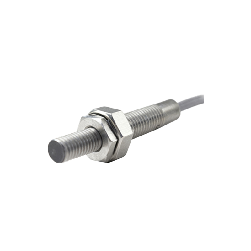
The standard wiring diagram for a two-wire 220V AC proximity sensor involves connecting it directly between the phase (hot) wire and the load. Here is a step-by-step breakdown:
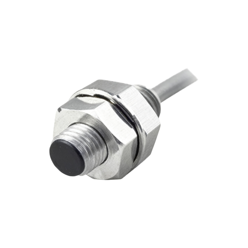
1. Power Supply Connection: Ensure the power source is a stable 220V AC supply, typically single-phase. Always verify the voltage with a multimeter before installation. For safety, disconnect power during wiring.
2. Sensor Connection: The sensor has two terminals, usually labeled or color-coded (e.g., brown for line/live and blue for load). Connect the brown wire to the 220V AC phase wire.
3. Load Connection: Connect the blue wire from the sensor to one terminal of the load (e.g., the A1 terminal of a contactor coil). The other terminal of the load should be connected to the neutral wire of the AC supply.
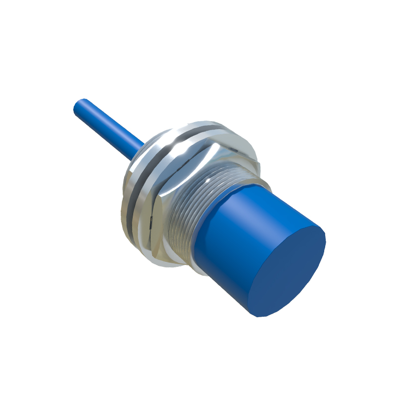
4. Grounding: Although not always mandatory, it is good practice to connect the sensor's grounding terminal (if available) to a proper earth ground for noise immunity and safety.
A typical circuit representation is:
AC Source (Phase) → Brown Wire (Sensor) → Internal Switch → Blue Wire (Sensor) → Load → AC Source (Neutral).
When the sensor detects an object, the internal switch closes, completing the circuit and energizing the load. When no object is present, the switch opens, de-energizing the load.
Critical installation considerations include:
- Load Compatibility: The load must be within the sensor's specified current range. If the load current is too low (below the minimum holding current), the sensor may not switch off reliably; if too high, it may overheat. For very low-power loads like PLC inputs, a shunt resistor (bleeder resistor) may be needed to ensure sufficient current flow for proper sensor operation.
- Leakage Current Management: Even when off, two-wire sensors allow a small leakage current to pass. This can cause issues with sensitive loads, such as keeping a relay slightly energized. To prevent this, connect a bypass resistor or capacitor in parallel with the load, as per the sensor manufacturer's recommendations.
- Wiring Practices: Use shielded cables in environments with high electromagnetic interference (EMI) to prevent false triggering. Keep sensor cables away from high-voltage power lines. Secure connections with appropriate terminals to avoid loose contacts, which can lead to arcing or voltage drops.
- Sensor Placement: Mount the sensor securely, ensuring the sensing face is free from obstructions like metal shavings or dust. Maintain the recommended sensing distance, as excessive gaps can reduce reliability.
Troubleshooting common issues often involves checking:
1. No Response from Load: Verify power supply voltage, sensor wiring continuity, and load integrity. Use a multimeter to measure voltage across the sensor terminals when activated; it should be near zero if functioning correctly.
2. Load Stays On: This could be due to excessive leakage current. Measure leakage current with the sensor off; if it exceeds the load's drop-out current, install a bypass resistor.
3. Intermittent Operation: Inspect for loose connections, environmental factors (e.g., temperature extremes), or EMI. Ensure the load current is within specifications.
In summary, two-wire 220V AC proximity sensors offer a compact