Proximity sensors are fundamental components in modern industrial automation, robotics, and safety systems. Their ability to detect the presence or absence of an object without physical contact makes them invaluable. While the external housing and sensing face are visible, the true intelligence lies within the internal circuitry. This article, written from an engineering perspective, delves into the typical internal circuit diagram of a standard inductive proximity sensor, explaining the function of each stage and its role in reliable object detection.
The core operational principle of an inductive proximity sensor is electromagnetic induction. It primarily detects metallic objects. The internal circuit is designed to generate an oscillating electromagnetic field from its sensing coil and monitor changes in that field caused by a metallic target entering its detection zone. A standard block diagram consists of five key stages: the Oscillator, Demodulator, Trigger, Output Stage, and Power Supply/Protection.
Stage 1: The Oscillator Circuit
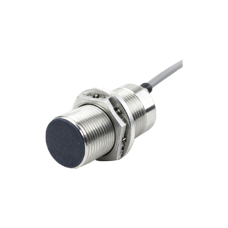
This is the heart of the sensor. The oscillator circuit typically uses a Colpitts or Hartley configuration, with the sensor's coil (L) forming part of the LC tank circuit alongside capacitors (C). An active component, usually a transistor or an integrated oscillator chip, sustains high-frequency oscillation (typically between 100 kHz and 1 MHz). When powered, this circuit generates a constant sinusoidal or near-sinusoidal alternating current through the coil, creating the alternating electromagnetic field at the active face. Under no-target conditions, the oscillator runs at its designed amplitude and frequency.
Stage 2: The Demodulator and Amplifier
The signal from the oscillator is fed into the demodulator stage. This stage, often a simple diode-based peak detector or an envelope detector circuit, converts the high-frequency AC signal into a DC voltage level proportional to the oscillation amplitude. This DC level is then passed through a filtering network to remove residual noise and is amplified. Under normal, no-target conditions, this DC signal is at its highest level.
Stage 3: The Trigger/Schmitt Trigger Circuit
The smoothed DC voltage from the demodulator is input into a trigger circuit, most commonly a Schmitt trigger. The Schmitt trigger is crucial for providing a clean, sharp switching action and inherent hysteresis. Hysteresis prevents output chatter when a target is at the very edge of the sensing range by having a higher turn-off threshold than the turn-on threshold. When a metallic target approaches the sensor face, it induces eddy currents in the target. These eddy currents draw energy from the oscillator's electromagnetic field, causing the oscillation amplitude to dampen or decay. This amplitude reduction is reflected as a drop in the DC voltage level from the demodulator. Once this voltage falls below the lower trigger point of the Schmitt trigger, the circuit state flips.
Stage 4: The Output Stage
The digital signal from the trigger circuit drives the output stage. This stage physically interfaces with the programmable logic controller (PLC) or other control systems. For a DC sensor, the output stage primarily consists of a switching semiconductor.
NPN (Sinking) Output: Uses an NPN transistor. The load is connected between the positive supply voltage and the output wire. The transistor switches the connection to ground (0V).
PNP (Sourcing) Output: Uses a PNP transistor. The load is connected between the output wire and ground. The transistor switches the connection to the positive supply voltage.
Analog Output (e.g., 4-20mA, 0-10V): Incorporates additional circuitry to convert the signal from the demodulator/amplifier stage into a proportional current or voltage, bypassing the digital trigger for continuous measurement.
The output stage is always protected by components like flyback diodes (for inductive loads) and current-limiting resistors.
Stage 5: Power Supply and Protection Circuitry
A regulated internal power supply ensures stable voltage for all internal ICs and transistors, independent of minor fluctuations in the external supply (e.g., 10-30V DC). This section includes reverse polarity protection, typically using a series diode or a MOSFET-based circuit, to prevent damage if power wires are connected incorrectly. Additional protection against voltage transients (TVS diodes) and short-circuit protection (e.g., a resettable fuse or current-limited regulator) are standard in robust industrial designs.
Practical Considerations from the Schematic
Understanding this internal layout aids in troubleshooting. For instance, if a sensor powers on (LED indicator lights) but does not detect targets, the issue likely lies in the oscillator, demodulator, or coil—perhaps due to a cracked ferrite core or a damaged capacitor in the LC tank. If the sensor is permanently "on," the fault could be in the trigger or output stage, such as a shorted output transistor. The inclusion of a status LED is often shown in parallel with the output or driven by