Capacitive proximity sensors are indispensable components in modern industrial automation, renowned for their ability to detect non-metallic objects such as plastics, liquids, and granular materials. However, their operational principle—based on changes in capacitance within an electrostatic field—makes them inherently susceptible to various forms of electrical and environmental interference. This susceptibility can lead to false triggering, reduced sensing range, or complete operational failure, compromising system reliability and safety. This article delves into the primary sources of interference for capacitive sensors and outlines robust engineering strategies to mitigate these effects, ensuring stable and accurate performance in demanding industrial environments.
The core of a capacitive sensor's operation involves generating an electrostatic field from its sensing face. When a target object enters this field, it alters the dielectric properties, causing a measurable change in capacitance that triggers the sensor's output. This high sensitivity, while advantageous for detection, also makes the sensor vulnerable to external influences. The primary interference sources can be categorized into three areas: electrical noise, environmental factors, and installation-related issues.
Electrical noise is arguably the most pervasive challenge. This includes electromagnetic interference (EMI) from nearby motors, variable frequency drives (VFDs), solenoids, and welding equipment, which can induce spurious voltages in the sensor's circuitry. Radio frequency interference (RFI) from communication devices and power line transients are also significant contributors. Such noise can be coupled into the sensor through conduction (via power and signal cables) or radiation (through the air).
Environmental factors encompass a wide range. Moisture, dust, oil, or conductive contaminants accumulating on the sensor face can alter the local dielectric constant, effectively "fooling" the sensor into detecting a permanent target. Extreme temperature fluctuations can affect the stability of internal electronic components and the dielectric properties of materials. Furthermore, the presence of non-target grounded objects or large metallic structures in the vicinity can distort the electrostatic field pattern.
Installation and configuration errors are often overlooked sources of problems. Incorrect mounting (e.g., flush vs. non-flush in metallic housings), inadequate grounding, improper cable routing parallel to high-voltage lines, and incorrect sensitivity adjustment can all introduce or amplify interference.
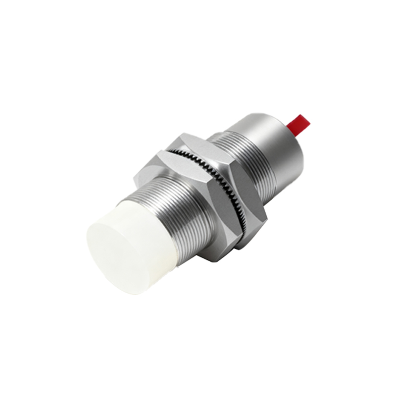
To combat these challenges, a multi-layered approach to anti-interference design and application is essential. First and foremost, proper sensor selection is critical. Choose sensors with robust metal housings that provide shielding against EMI/RFI. Many modern sensors incorporate advanced features such as embedded shielding rings that focus the electrostatic field, reducing sensitivity to lateral interference. Sensors with built-in diagnostics or immunity ratings (e.g., against specific EMI levels) should be prioritized for noisy environments.
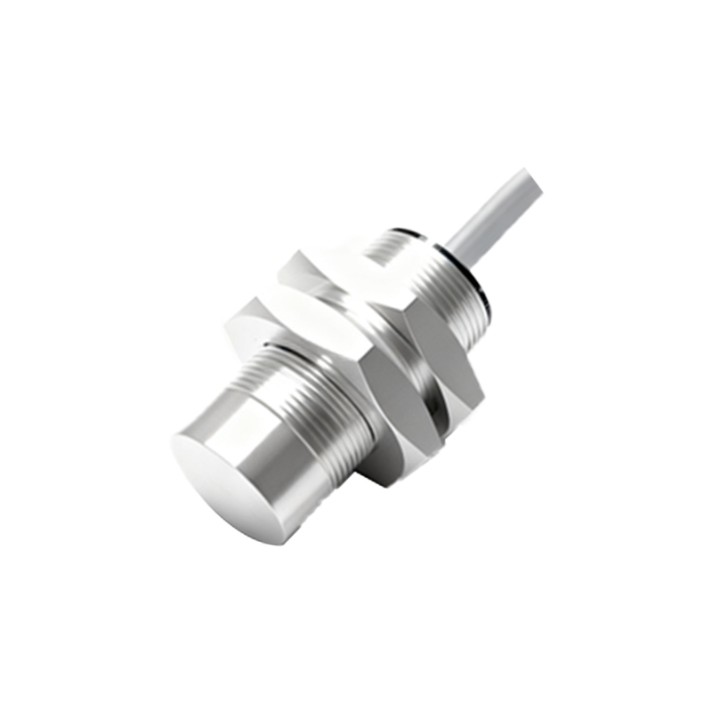
Shielding and grounding constitute the cornerstone of electrical noise suppression. Always use shielded cables, typically with a braided copper shield, for both power and signal connections. The shield must be grounded at only one point, preferably at the controller or PLC end, to prevent ground loops. The sensor housing itself should be securely grounded to the machine frame or a dedicated earth ground, providing a low-impedance path for noise currents. Ferrite cores or beads installed on cables near the sensor connector can effectively suppress high-frequency noise.
Installation best practices are non-negotiable. Maintain adequate physical separation between sensor cables and high-power cables. A minimum distance of 20-30 cm is recommended, and cables should cross at right angles if they must intersect. For sensors in non-flush mounting applications, ensure the recommended clearance from surrounding metal is maintained to prevent field distortion. Regularly clean the sensor face to prevent buildup of contaminants. In environments with conductive dust or sprays, consider sensors with specialized coatings or protective boots.
Circuit design and configuration offer further defense. Utilizing sensors with DC (typically 3-wire) outputs instead of AC can reduce susceptibility to some forms of noise. For analog sensors, using a 4-20 mA current loop signal is inherently more noise-resistant than a 0-10V voltage signal. When configuring sensitivity, use the "teach-in" or calibration function with the actual target present, and set the threshold with a sufficient margin (typically 20-30% above the trigger point) to account for minor environmental drift without making the sensor blind to genuine targets. In programmable logic controllers (PLCs), implementing software debounce filters or delay timers can ignore transient false signals.
For extreme cases, additional external measures may be required. Installing the sensor within a grounded metallic enclosure (with a non-metallic window for sensing) can provide exceptional isolation. Using isolated power supplies for sensor circuits can break ground loops. In areas with intense RFI, consulting with specialists for additional filtering or shielding may be necessary.
In conclusion, while capacitive proximity sensors are sensitive to interference, a systematic understanding of noise sources combined with rigorous application of shielding, grounding, proper installation, and careful configuration can effectively neutralize these threats. By adhering to these engineering best practices, reliability can be