In industrial automation and machinery, proximity sensors are critical components for non-contact detection of objects. They ensure precise positioning, counting, and safety functions. When a proximity sensor fails, it can lead to unexpected downtime, production errors, or even safety hazards. Recognizing the signs of failure and knowing how to properly replace the sensor are essential skills for maintenance technicians and engineers. This guide provides a detailed, industry-standard procedure for replacing a faulty inductive or capacitive proximity sensor.
Recognizing Symptoms of a Failed Proximity Sensor
Before initiating a replacement, confirm the sensor is indeed faulty. Common failure indicators include:
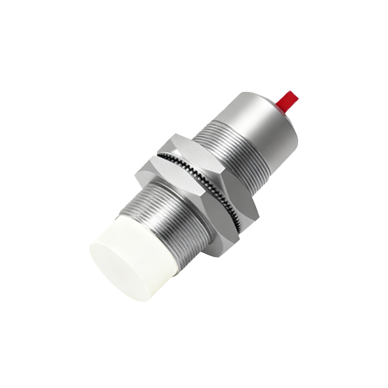
Intermittent or No Detection: The sensor fails to detect a target within its specified sensing range consistently or at all.
Erratic Output: The output signal (PNP/NPN, NO/NC) fluctuates without a corresponding change in target position.
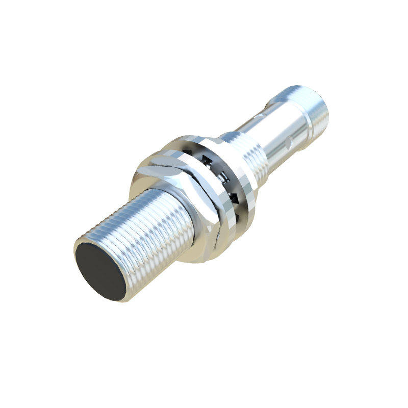
LED Indicator Malfunction: The sensor's built-in LED (often indicating power or output status) remains off, stays on constantly, or behaves irregularly.
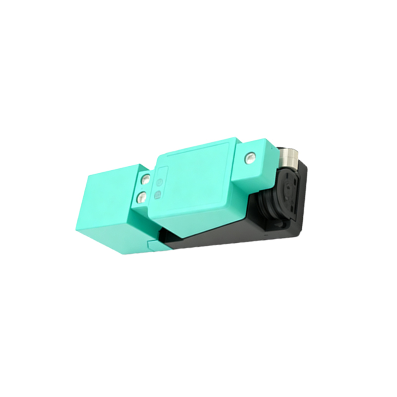
Physical Damage: Visible signs such as cracked housing, damaged sensing face, or bent/broken connectors.
Short Circuit or Overload Warnings: The connected PLC or controller registers a fault related to the sensor's circuit.
Always perform preliminary checks: verify power supply voltage, check wiring for loose connections or breaks, and ensure the target object is suitable (correct material, size, and within range). Use a multimeter to measure output voltage/current under activation. Consult the sensor's datasheet for specific testing procedures.
Safety First: Pre-Replacement Protocol
1. Power Down: Completely isolate and lock out/tag out (LOTO) all energy sources to the machine or control panel supplying the sensor. This includes electrical, pneumatic, and hydraulic systems as applicable.
2. Confirm Zero Energy: Use a properly rated voltage tester to verify the circuit is de-energized.
3. Personal Protective Equipment (PPE): Wear appropriate PPE, including safety glasses, insulated gloves, and protective clothing.
4. Documentation: Review the machine's electrical diagrams and the sensor's technical datasheet. Note the sensor's part number, type (inductive/capacitive), sensing range, output configuration, voltage rating, thread size, and wiring connections.
Step-by-Step Replacement Procedure
Step 1: Removal of the Faulty Sensor
Disconnect Wiring: At the sensor connection point (typically a quick-disconnect M12/M8 connector or individual leads), carefully disconnect the cables. If it's a pre-wired model with leads connected to a terminal block, note or photograph the wire color/terminal assignment before loosening the terminals.
Unmount the Sensor: Using the correct tool (often a wrench), unscrew the sensor from its mounting bracket or housing. Note any locking nuts or washers. For cylindrical sensors, avoid damaging the threads. Gently extract the sensor.
Step 2: Preparation and Installation of the New Sensor
Verify Replacement: Ensure the new sensor is an exact match or a approved equivalent. Cross-check part numbers, specifications, and physical dimensions.
Pre-Installation Check: If possible, bench-test the new sensor with a known target and a safe power source to confirm basic functionality before installation.
Mounting: Screw the new sensor into the mounting location. Do not overtighten, as this can damage the housing or threads. Follow the manufacturer's specified torque. Ensure the sensing face is correctly oriented and unobstructed.
Wiring: Reconnect the wiring. For quick-disconnect types, simply plug in the connector, ensuring it clicks securely. For terminal connections, meticulously re-establish the wiring according to your notes or photo: typically, brown wire to DC+, blue wire to DC-, and black (or white) wire to the signal input. Ensure terminals are tight.
Step 3: Commissioning and Testing
Visual Inspection: Double-check all connections and mounting.
Restore Power: Following LOTO removal procedures, carefully restore power to the system.
Function Test: Manually introduce a valid target object into the sensor's detection field. Observe the sensor's LED indicator for correct on/off response.
System Integration Test: Operate the machine through its normal cycle to verify the sensor triggers the correct sequence in the PLC or control system. Monitor for consistency.
Adjustment (if necessary): Some sensors feature a potentiometer for sensitivity adjustment. Fine-tune if required to achieve reliable detection without false triggers. Refer to the datasheet for adjustment guidelines.
Post-Replacement Best Practices