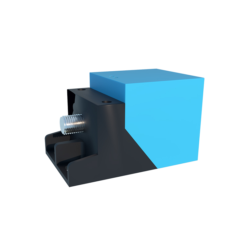
In industrial automation and control systems, inductive proximity sensors are indispensable for non-contact detection of metallic objects. Their reliability, durability, and solid-state design make them a preferred choice for countless applications, from machine tool positioning to conveyor belt monitoring. However, a common and often perplexing issue encountered by maintenance engineers and system integrators is a sensor exhibiting a "slow" or "sluggish" response. This delay between the target's presence and the sensor's output signal switching can lead to missed counts, imprecise positioning, and ultimately, production line inefficiencies or quality defects. Understanding the root causes of this sluggishness is the first critical step toward implementing an effective solution.
Fundamentally, an inductive proximity sensor operates by generating an electromagnetic field via an internal oscillator coil. When a metallic target enters this field, eddy currents are induced on the target's surface. These currents absorb energy from the oscillator, causing its amplitude to decrease. This change is detected by the sensor's circuitry, which then triggers a change in the output state (e.g., from OFF to ON). The speed of this entire process is characterized by the sensor's response time, typically specified in milliseconds (ms) or microseconds (µs) in the datasheet. A perceived "slow" response often means the actual performance is falling short of this specification or the application's required timing.
Several technical factors can contribute to a delayed response. First and foremost is target characteristics. The sensor's rated operating distance (Sn) is calibrated for a standard mild steel target of a specified size. Using a target made of a different metal, such as aluminum, brass, or stainless steel, reduces the effective sensing distance due to lower permeability and/or conductivity. If the target is too small or too thin, it may not sufficiently dampen the oscillator, causing the sensor to trigger inconsistently or only at impractically close distances, which can be misinterpreted as slowness. The target must meet or exceed the minimum size specifications for reliable operation.
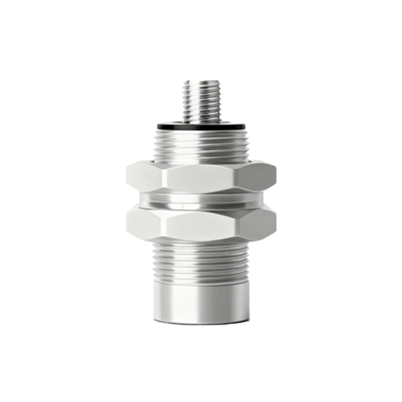
Environmental and installation factors play a significant role. The presence of other metals in the sensing field—mounting brackets, machine frames, or even other sensors in close proximity—can cause electromagnetic interference or shielding effects. This can pre-dampen the oscillator, reducing its sensitivity and effective range, leading to a delayed switch as the target must come much closer to trigger the threshold. Incorrect mounting, such as not allowing the recommended lateral clearance from surrounding metal, exacerbates this issue. Furthermore, extreme temperatures can affect the electronic components' performance. High temperatures, in particular, can increase the resistance of the coil and slow down the response of semiconductor switching elements, while very low temperatures might affect capacitor characteristics.
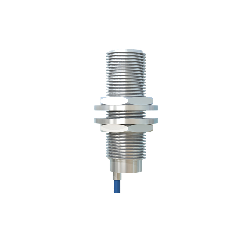
Electrical considerations are equally crucial. A weak or unstable power supply voltage can directly impact the sensor's internal circuitry and its ability to switch the output transistor cleanly and quickly. Voltage drops, especially in long cable runs or under high load conditions, are a common culprit. Additionally, electrical noise from variable frequency drives (VFDs), welding equipment, or large motors can induce false signals or interfere with the sensor's oscillator. This noise can cause the output to chatter or require additional filtering by the sensor's internal electronics, which inherently adds a delay to the response. The load connected to the sensor output also matters. Exceeding the maximum switching current or capacitive load can slow down the transistor's switching speed.
Finally, the sensor itself may be the source. Wear and tear over time, physical damage to the sensing face, or internal component degradation can all lead to performance decay. Contamination is a major factor; a buildup of metallic dust, chips, or grease on the active sensing face can act as a permanent or intermittent target, saturating the field and dramatically reducing sensitivity to the actual target.
Addressing a slow response requires a systematic diagnostic approach. Begin by verifying the target material, size, and approach speed against the sensor's datasheet. Ensure the installation complies with all clearance requirements. Measure the power supply voltage at the sensor's terminals during operation to rule out voltage drops. Inspect the sensing face for contamination and clean it thoroughly with a non-abrasive cloth and appropriate solvent. Check for sources of electrical noise and consider using shielded cables, proper grounding, and installing noise filters if necessary. If possible, test the sensor with a known-good target in a controlled environment to isolate the issue. Consulting the manufacturer's technical support, with the specific model and application details, can provide invaluable guidance for complex scenarios. By methodically eliminating these potential causes, engineers can restore the swift and reliable operation essential for maintaining optimal system performance.