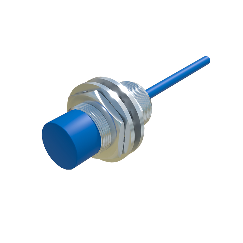
Proximity sensors are essential components in industrial automation, robotics, and safety systems, detecting the presence or absence of objects without physical contact. As an electrical engineer, ensuring these sensors function correctly is critical for system reliability. One of the most practical methods for troubleshooting proximity sensors is using a digital multimeter (DMM). This guide provides a step-by-step approach to testing both inductive and capacitive proximity sensors with a multimeter, adhering to standard industry practices.
Before testing, always prioritize safety. Disconnect power to the sensor circuit to prevent electrical shock or damage. Verify the sensor type—inductive sensors detect metallic objects, while capacitive sensors respond to both metallic and non-metallic materials. Check the datasheet for specifications such as operating voltage, output type (PNP/NPN), and sensing range. Gather your tools: a digital multimeter with DC voltage, resistance, and continuity functions, along with appropriate test leads.
For inductive proximity sensors, start by testing the power supply. Set the multimeter to DC voltage mode (typically 20V range). Reconnect power to the sensor. Place the multimeter’s black lead on the negative terminal or ground wire, and the red lead on the positive supply wire (usually brown wire for +V, blue for 0V). The reading should match the rated voltage (e.g., 10-30V DC). If voltage is absent or unstable, inspect the power source and wiring.
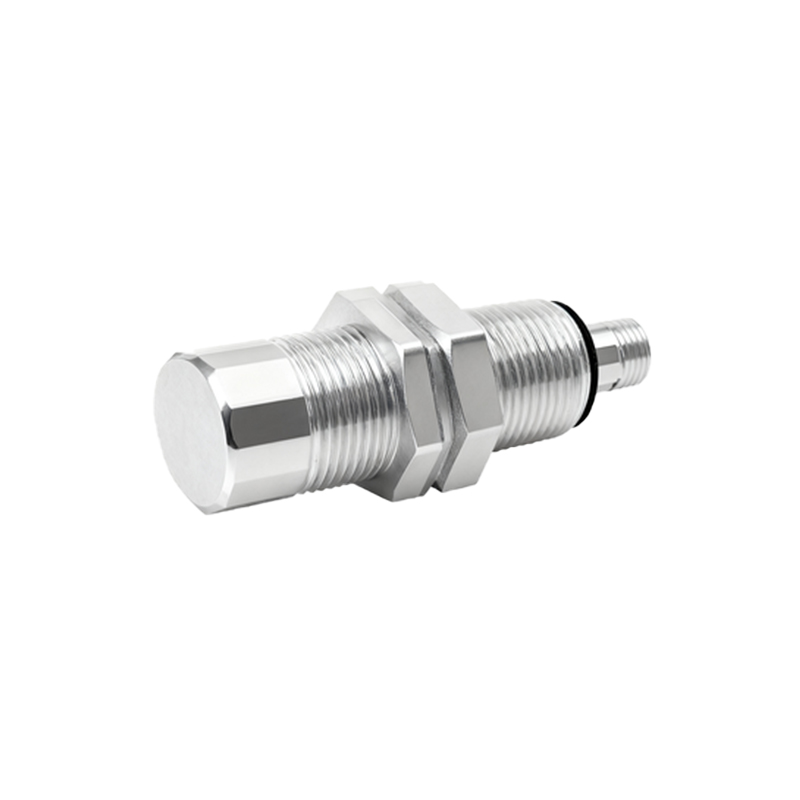
Next, test the sensor output. Identify the output wire (often black for NPN or white for PNP). With power applied, use the multimeter in DC voltage mode. Connect the black lead to ground and the red lead to the output wire. Without a target object near the sensor, note the voltage. For an NPN sensor (sinking output), it should read near supply voltage; for a PNP (sourcing output), it should read near 0V. Then, introduce a metal target within the sensing range. The voltage should switch: NPN drops to near 0V, while PNP rises to supply voltage. If no change occurs, the sensor may be faulty.
For capacitive proximity sensors, the process is similar but requires attention to material detection. Test power supply as described above. Then, check output voltage with and without a target (e.g., plastic or liquid). Capacitive sensors often have sensitivity adjustments; ensure these are set correctly. If output doesn’t toggle, use the multimeter’s continuity or resistance mode to test for internal shorts or opens. Disconnect power and measure resistance between output and ground—abnormally low or high readings indicate damage.
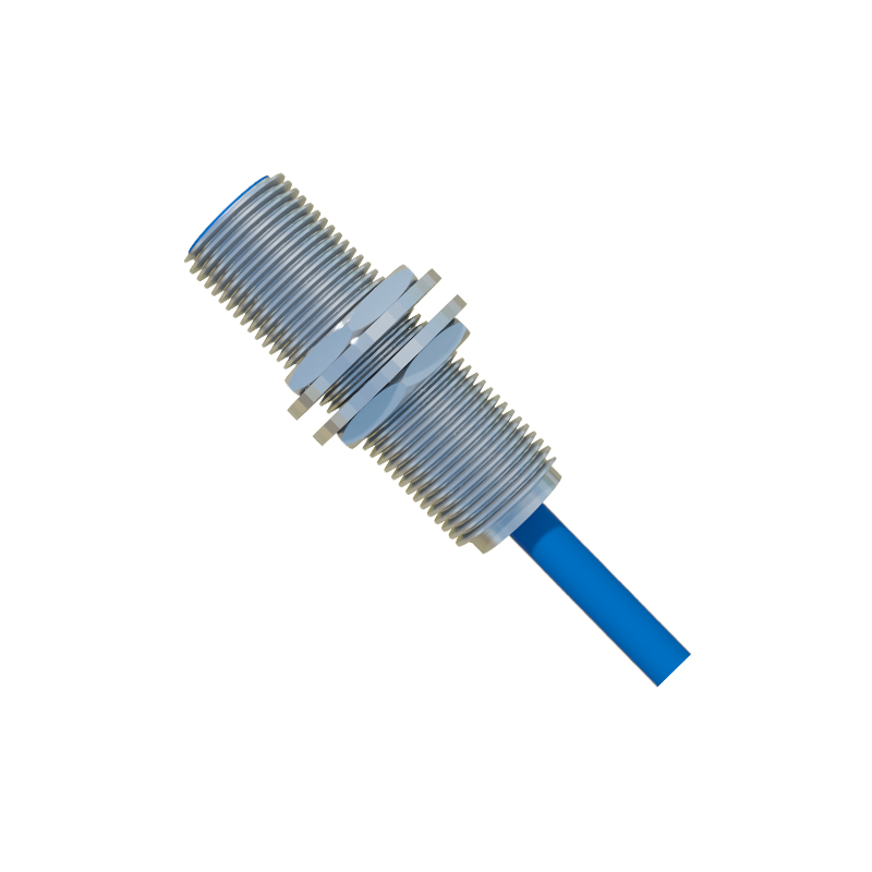
Additionally, multimeters can diagnose wiring issues. Use continuity mode (with power off) to check for broken wires or poor connections between the sensor and controller. A beep indicates good continuity; no sound suggests a break. Also, measure insulation resistance if environmental factors like moisture are suspected, though a megohmmeter is preferred for high-voltage checks.
Common pitfalls include ignoring load compatibility—ensure the multimeter’s impedance doesn’t affect readings when testing low-current outputs. Always refer to manufacturer guidelines, as some sensors require specific test procedures. For instance, certain models have diagnostic LEDs that complement multimeter readings.
In summary, a digital multimeter is a versatile tool for validating proximity sensor operation. By methodically testing voltage, output response, and continuity, engineers can quickly isolate faults, reduce downtime, and maintain system integrity. Regular preventive checks with a multimeter can also extend sensor lifespan, ensuring optimal performance in demanding industrial environments.