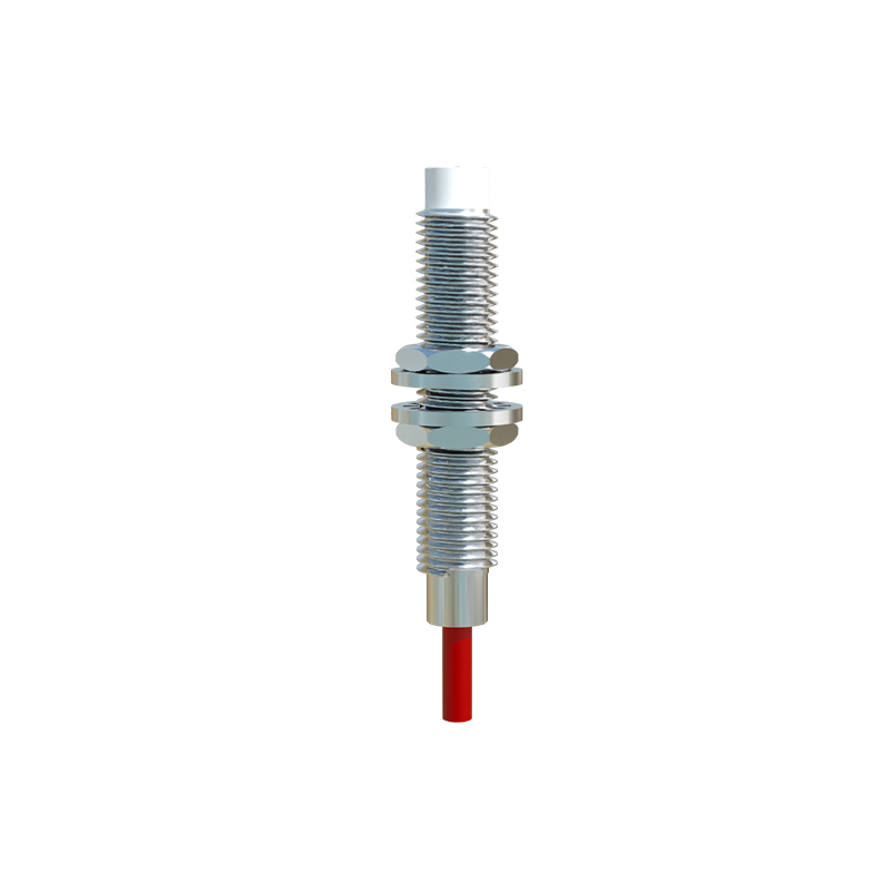
In industrial automation and control systems, proximity switch sensors are critical components for detecting the presence or absence of objects without physical contact. Proper wiring is essential to ensure reliable operation, safety, and system integrity. This guide provides a comprehensive overview of how to distinguish and connect wiring for proximity switch sensors, covering key principles, standards, and practical steps.
Proximity switches typically come in two main types based on output configuration: PNP (sourcing) and NPN (sinking). Understanding this distinction is the first step in wiring. PNP sensors switch the positive voltage to the load, meaning the output wire provides a positive signal when activated. In contrast, NPN sensors switch the negative or ground side, providing a ground path when triggered. Most sensors have three wires: brown (positive), blue (negative), and black (output). However, some models may include additional wires for diagnostic or special functions, such as white for complementary output or shield wires for noise reduction.
To correctly distinguish wiring, start by consulting the sensor's datasheet or manual, which specifies the wire colors and functions according to international standards like IEC 60947-5-2. Generally, brown connects to the positive DC supply (e.g., +24V), blue to the negative or common ground, and black to the load (e.g., PLC input or relay). For AC-powered sensors, wiring may involve live (brown) and neutral (blue) connections, with output often in black. Always verify voltage ratings—common DC sensors operate at 10-30V DC, while AC models may use 20-250V AC.
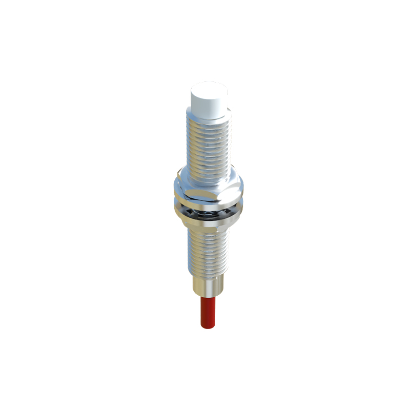
When installing, use a multimeter to test continuity and voltage if labels are unclear. For DC sensors, power the unit and measure between blue and black: PNP types show near-supply voltage when active, while NPN types read near zero. Ensure proper grounding to prevent electrical noise, especially in environments with motors or frequency drives. Shielded cables are recommended for long runs or high-interference areas, with the shield grounded at one end to avoid ground loops.
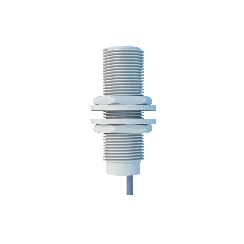
Safety is paramount: disconnect power before wiring, and follow lockout-tagout procedures. Match wire gauges to current requirements—typically 18-22 AWG for low-current sensors. For multi-sensor setups, avoid daisy-chaining power wires; instead, use a dedicated distribution block to prevent voltage drops. Color-coding aids troubleshooting: brown for power, blue for ground, and black for signal is industry-standard, but always double-check as variations exist by manufacturer.
In summary, distinguishing proximity sensor wiring hinges on identifying PNP vs. NPN outputs, adhering to color codes, and verifying with tools. Correct wiring enhances sensor longevity and system performance, reducing downtime in applications like conveyor systems, robotics, or safety interlocks. For complex systems, consider consulting an electrical engineer to ensure compliance with local regulations and optimal integration.