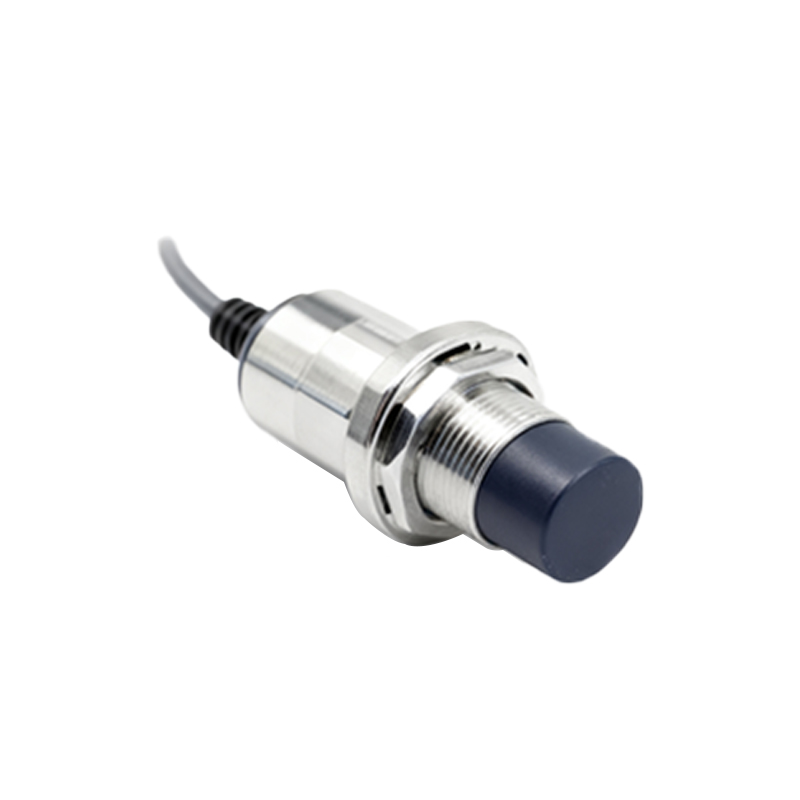
In the realm of industrial automation and control systems, proximity sensor switches stand as fundamental components for non-contact object detection. Their robust and reliable structure is key to their performance in diverse and often harsh environments. This article delves into the core structural composition of common proximity sensor types, namely inductive, capacitive, and photoelectric, from an engineering perspective.
The fundamental architecture of a standard proximity sensor can be deconstructed into several critical internal and external components. Externally, the housing or body provides mechanical integrity and environmental protection, typically rated with an IP (Ingress Protection) code. This casing is commonly constructed from materials like nickel-plated brass, stainless steel, or rugged plastics (PBT), chosen for their durability and resistance to chemicals, oils, and physical impact. Integral to the housing is the sensing face, a front surface through which the detection field emanates. For inductive sensors, this face is often a ferrite core assembly.
Internally, the heart of an inductive proximity sensor is an oscillator circuit that generates a high-frequency electromagnetic field at the sensing face. This field is contained within a coil wound around a ferrite core. When a metallic target enters this oscillating field, eddy currents are induced on the target's surface. These currents absorb energy from the oscillator, causing its amplitude to decrease. This change is detected by a threshold circuit (often a Schmitt trigger), which subsequently switches the state of the output stage. The output stage, comprising a solid-state transistor (PNP or NPN sourcing/sinking), provides the switching signal to the controller (PLC). All these electronic components are mounted on a printed circuit board (PCB) and potted with a resin compound to dampen vibrations, provide thermal management, and prevent moisture ingress.
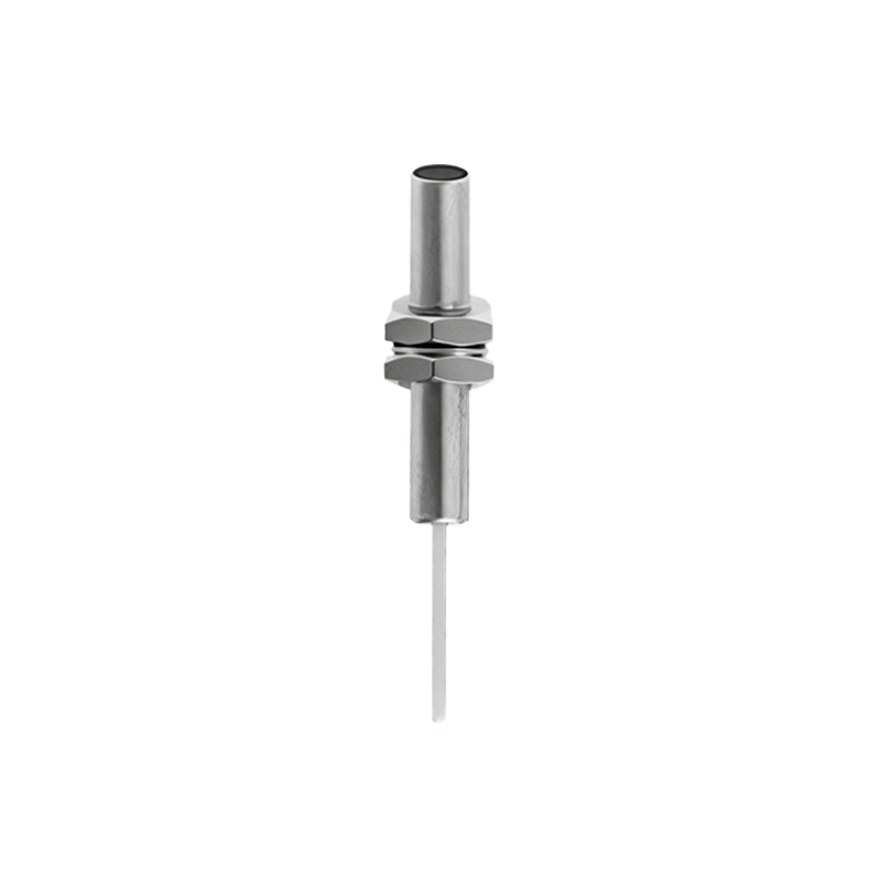
Capacitive proximity sensors share a similar external structure but differ internally. They utilize a capacitor formed by the sensor's face (one plate) and the ground (or the sensor's housing as the other plate). The oscillator circuit is tuned to the capacitance of this arrangement. The approach of any material (conductive or non-conductive) alters the dielectric constant and thus the capacitance, which shifts the oscillator's frequency or amplitude. This shift is evaluated, leading to an output switch. Structurally, they often include a sensitivity adjustment potentiometer accessible from the exterior.
Photoelectric sensors, while serving a similar function, employ a distinctly different structural philosophy. Their housing contains separate, precisely aligned compartments for the emitter (light source – typically an LED producing visible red, infrared, or laser light) and the receiver (a phototransistor or photodiode). In a thru-beam type, these are in two separate housings. In a retro-reflective or diffuse (proximity) type, they are housed together. The optical components are protected by precision-molded lenses. The internal structure includes the driver circuit for the emitter, a highly sensitive amplifier circuit for the receiver, and a logic circuit to process the signal against a set threshold. Alignment stability and protection of the optical path from contamination are critical structural considerations.
A crucial structural element common to most DC-powered industrial proximity switches is the inclusion of protective circuits. These typically involve reverse polarity protection diodes, surge suppression, and short-circuit protection for the output transistor. For AC/DC universal types, a rectifier bridge is a standard internal component. Wiring is facilitated via pre-wired cables or quick-disconnect (QD) connectors, which are integrated into the housing design with effective strain relief.
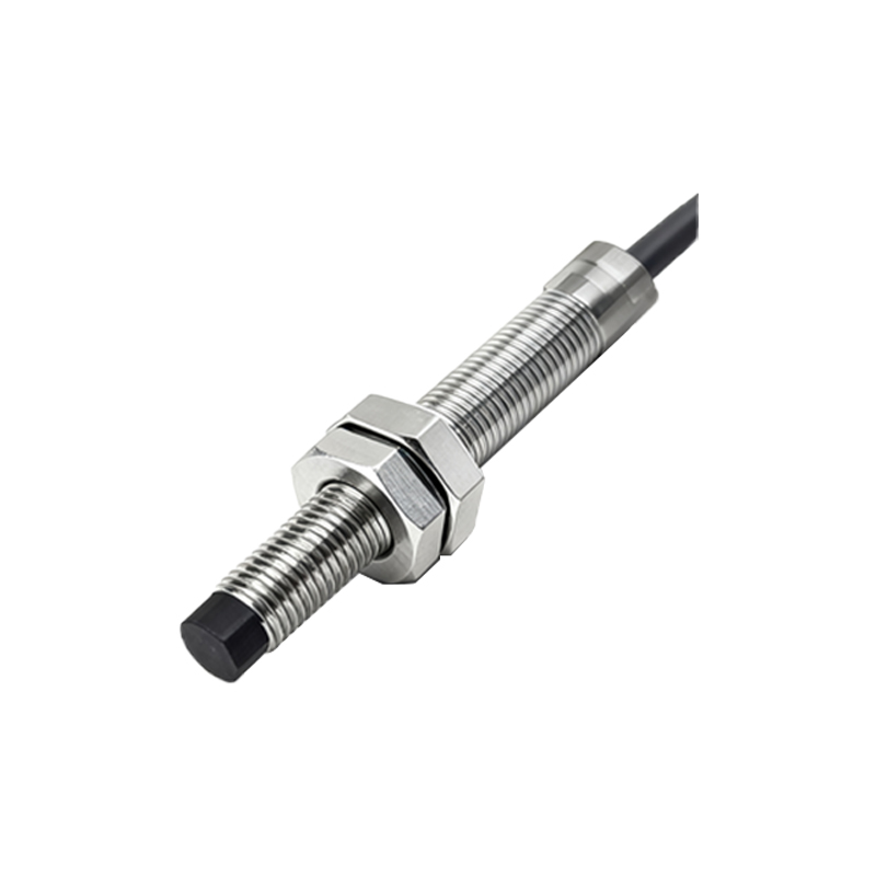
The structural design directly dictates key performance parameters. The size of the coil and oscillator in an inductive sensor determines its nominal sensing distance (Sn). The housing material and shielding type (shielded/embeddable vs. unshielded/non-embeddable) affect the magnetic field's shape and the sensor's immunity to adjacent metal. Shielded sensors have a metal ring surrounding the coil, confining the field radially, allowing flush mounting in metal. Unshielded sensors have a longer range but require a non-metallic surround.
In conclusion, the sophisticated yet robust structure of a proximity sensor switch—encompassing the protective housing, sensing element, oscillator, detector circuit, output stage, and integral protection—is a testament to applied electrical engineering. Understanding this physical and electronic architecture is essential for proper selection, installation, and troubleshooting, ensuring optimal reliability in automated systems where precise, maintenance-free detection is paramount.