Magnetic proximity sensors are widely used in industrial automation, automotive systems, and safety applications due to their non-contact detection capability, durability, and reliability. Understanding the structural diagram of these sensors is crucial for engineers and technicians involved in design, installation, and maintenance. This article provides a detailed breakdown of the key components and working principles based on a standard magnetic proximity sensor structural diagram.
A typical magnetic proximity sensor consists of several core components, as illustrated in a standard structural diagram. The primary elements include the sensor housing, sensing element (often a reed switch or Hall-effect chip), magnet, signal conditioning circuitry, and output interface. The housing is usually made of robust materials like stainless steel, brass, or PBT plastic to protect internal components from environmental factors such as moisture, dust, and mechanical impact. It ensures the sensor can operate in harsh industrial conditions, with common IP ratings ranging from IP67 to IP69K for resistance to water and dust ingress.
At the heart of the sensor is the sensing element. In reed switch-based sensors, the diagram shows two ferromagnetic reeds sealed within a glass tube filled with inert gas. When a magnetic field from a target (e.g., a permanent magnet or ferrous object) approaches, the reeds magnetize and attract each other, closing the electrical circuit to generate an output signal. In Hall-effect sensors, the structural diagram depicts a semiconductor chip that produces a voltage proportional to the magnetic field strength when exposed to it. This voltage is then processed by integrated circuitry. The choice between reed and Hall-effect types depends on factors like switching speed, lifespan, and sensitivity—reed switches offer simple, low-power operation, while Hall-effect sensors provide higher precision and durability for high-frequency applications.
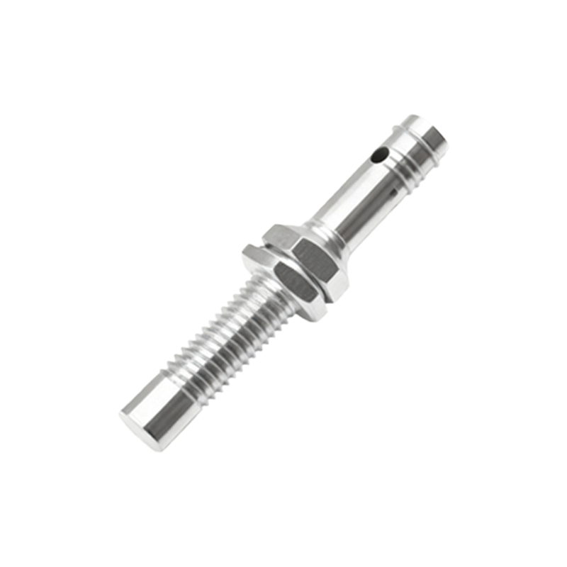
The magnet is a critical external component in the system, often shown separately in diagrams for inductive or magnetic-operated sensors. It can be integrated into a moving target (like a machine part) or mounted opposite the sensor. The structural diagram typically indicates the sensing distance, which varies based on magnet strength and sensor design, commonly ranging from a few millimeters to over 50 mm. Proper alignment between the magnet and sensor, as per diagram guidelines, is essential for reliable detection to avoid false triggers or missed signals.
Signal conditioning circuitry, embedded within the housing, is another key part illustrated in the diagram. This includes amplifiers, comparators, and filters that convert the raw signal from the sensing element into a clean, stable output. For digital sensors, the diagram may show Schmitt triggers to provide hysteresis, reducing noise and ensuring crisp switching even with slow-moving targets. Power supply connections are also detailed, with most sensors operating on DC voltages (e.g., 5V to 30V) or AC in some models. The output interface, depicted with terminals or connectors, can be analog (e.g., 0-10V or 4-20mA) or digital (e.g., PNP/NPN transistor or relay outputs), allowing integration with PLCs, controllers, or other automation devices.
The working principle, derived from the structural diagram, involves magnetic field interaction. When a target enters the sensor’s detection zone, it alters the magnetic flux density, triggering the sensing element. In reed switches, this causes contact closure; in Hall-effect sensors, it changes output voltage. The signal conditioning circuit then processes this change, producing an output that indicates presence or absence of the target. Diagrams often include timing charts or response curves to illustrate switching behavior, including response time (typically microseconds to milliseconds) and repeatability.
Installation and wiring are guided by the structural diagram, which shows mounting holes, dimensions, and connection points. Engineers must follow these specifications to ensure optimal performance—for instance, avoiding metal-to-metal contact that could interfere with magnetic fields. Maintenance tips based on the diagram include checking for magnet degradation or housing damage, as these can affect sensing accuracy. Common applications highlighted in such diagrams include position sensing in cylinders, speed detection in conveyors, and safety interlocks in machinery.
In summary, a magnetic proximity sensor structural diagram serves as a vital tool for understanding device composition and functionality. By analyzing each component—from housing and sensing element to circuitry and output—engineers can select, implement, and troubleshoot sensors effectively. This knowledge enhances system reliability and efficiency in diverse industrial settings, making magnetic proximity sensors a cornerstone of modern automation.