Laser sensors are widely used across various industries for precision measurement, object detection, and automation control due to their high accuracy and reliability. However, a common issue encountered by engineers and technicians is when a laser sensor appears to have no current output, often indicated by a lack of signal or a reading of zero in current-loop-based systems (e.g., 4-20 mA outputs). This problem can halt production lines, cause measurement failures, and lead to significant downtime if not addressed promptly. Understanding the root causes and applying systematic troubleshooting steps are essential for maintaining operational efficiency.
First, it is crucial to differentiate between the sensor having no current output and the sensor simply not detecting a target. A laser sensor with a current output, typically 4-20 mA, provides an analog signal proportional to the measured parameter, such as distance or presence. When the sensor shows no current, it means the output circuit is not generating the expected electrical signal, even if the laser emitter might be functioning visibly. Common reasons for this issue include power supply problems, wiring faults, configuration errors, sensor damage, or incompatible load resistance.
Power supply issues are among the most frequent culprits. Laser sensors require a stable DC voltage, commonly 12-24 VDC, to operate correctly. If the voltage is too low, absent, or unstable, the sensor may not power on fully, leading to no current output. Engineers should verify the power supply voltage at the sensor's terminals using a multimeter. Ensure that the polarity is correct (positive to positive, negative to negative) as reverse polarity can damage internal circuits. Additionally, check for adequate current capacity; an overloaded power supply might drop voltage under load.
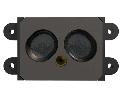
Wiring and connection faults are another major cause. Loose, corroded, or broken wires in the power or output lines can interrupt the current flow. Inspect all cable connections, terminals, and connectors for integrity. In 4-20 mA output systems, the current loop must be complete; an open circuit will result in zero current. Verify that the load resistor (usually 250-500 ohms) is properly connected across the output terminals and is within the sensor's specified range. A missing or burned-out load resistor can prevent current reading. Also, check for short circuits in the wiring that might divert current away from the measurement point.
Configuration and setting errors can also lead to no current output. Many laser sensors have configurable output types (e.g., NPN/PNP, analog, switch) and ranges. If the sensor is set to a different output mode than expected, such as a voltage output instead of current, or if the output is disabled via software, it will not produce a 4-20 mA signal. Consult the sensor's manual to ensure the output is configured correctly for current analog operation. Some sensors feature diagnostics or status LEDs; a red or flashing LED might indicate a configuration fault or error state.
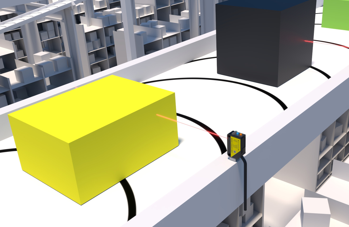
Sensor damage or internal failure is a possibility, especially in harsh environments. Overvoltage, electrical surges, excessive vibration, moisture ingress, or extreme temperatures can damage the laser diode, processing circuitry, or output transistor. If basic checks on power, wiring, and configuration yield no issues, the sensor itself may be faulty. Perform a basic functional test: with proper power and a known target within range, measure the output current directly at the sensor's output pins (disconnected from the control system). If there is still no current, the sensor likely requires replacement. Additionally, check for physical damage to the lens or housing.
Compatibility with the control system is often overlooked. The receiving device (e.g., PLC, controller) must be configured to accept a 4-20 mA input on the correct channel. An incorrect input type setting on the PLC, such as expecting a voltage signal, will show zero. Ensure the control system's input module matches the sensor's output specifications. Also, ground loops or noise interference in industrial settings can sometimes suppress small current signals; using shielded cables and proper grounding techniques can mitigate this.
In summary, troubleshooting a laser sensor with no current output involves a step-by-step approach: verify power supply quality, inspect all wiring and connections, confirm correct sensor configuration, test the sensor independently, and ensure compatibility with the control system. Documenting maintenance procedures and keeping spare sensors on hand can reduce downtime. Regular preventive maintenance, including cleaning lenses and checking electrical connections, helps avoid such issues. By methodically addressing these areas, engineers can quickly restore sensor functionality and maintain the reliability of automated systems, ensuring continuous and efficient industrial operations.