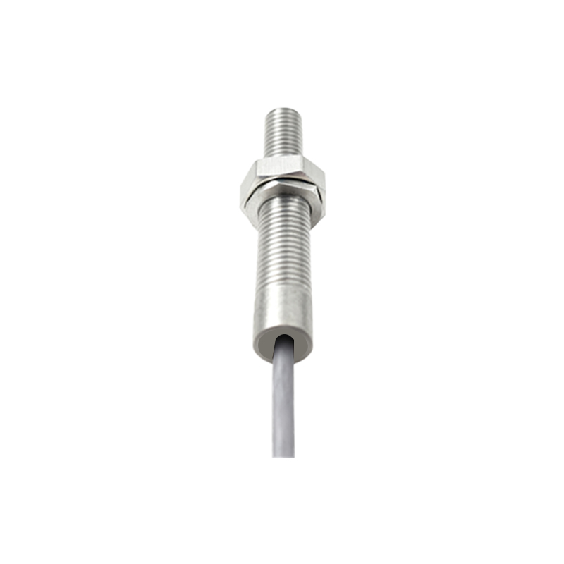
Proximity sensors are critical components in modern pneumatic valve systems, providing non-contact detection of valve position to ensure precise control and reliable operation in industrial automation. Proper installation is paramount to achieving optimal performance, longevity, and safety. This guide details the essential steps and considerations for installing proximity sensors on pneumatic valves, adhering to industry best practices.
The first step involves thorough preparation. Before any installation begins, ensure the pneumatic system is depressurized and isolated from its power source to prevent accidental actuation. Confirm the compatibility of the selected inductive proximity sensor with the valve's actuator material (typically ferrous metals like steel for inductive sensors) and the required sensing distance. Gather necessary tools, including appropriate wrenches, a mounting bracket or clamp specific to the valve model, and the sensor's datasheet for wiring and adjustment specifications.
Mounting the sensor is the core physical task. Most pneumatic actuators feature pre-drilled holes or standardized slots (e.g., per ISO 5211 or NAMUR standards) for sensor attachment. If using a bracket, securely fasten it to the actuator body, ensuring it does not interfere with the valve's movement or external piping. The sensor itself is then mounted into the bracket. The critical adjustment is the air gap—the distance between the sensor's sensing face and the target, which is usually a cam or a specific feature on the valve's piston or rotary shaft. This gap must be set precisely according to the manufacturer's specifications, typically between 1 to 2 mm. An incorrect gap can lead to failure to detect or erratic signals. Tighten the sensor's locking nut firmly to prevent vibration-induced displacement, but avoid over-torquing which may damage the housing.
Electrical wiring follows mechanical mounting. Run the sensor's cable through a conduit or cable carrier for protection against physical damage, oils, and coolants. Connect the wires to the designated controller input module—commonly a PLC (Programmable Logic Controller). Standard 3-wire DC sensors (PNP or NPN) require connection to a DC power supply (often 10-30 VDC), the signal output wire, and the ground. Always adhere to the color-coding (e.g., brown for +V, blue for 0V, black for signal) and wire according to the system's schematic. Ensure all connections are tight and properly insulated. Implementing shielded cables is highly recommended in electrically noisy industrial environments to prevent electromagnetic interference (EMI) from affecting the signal integrity.
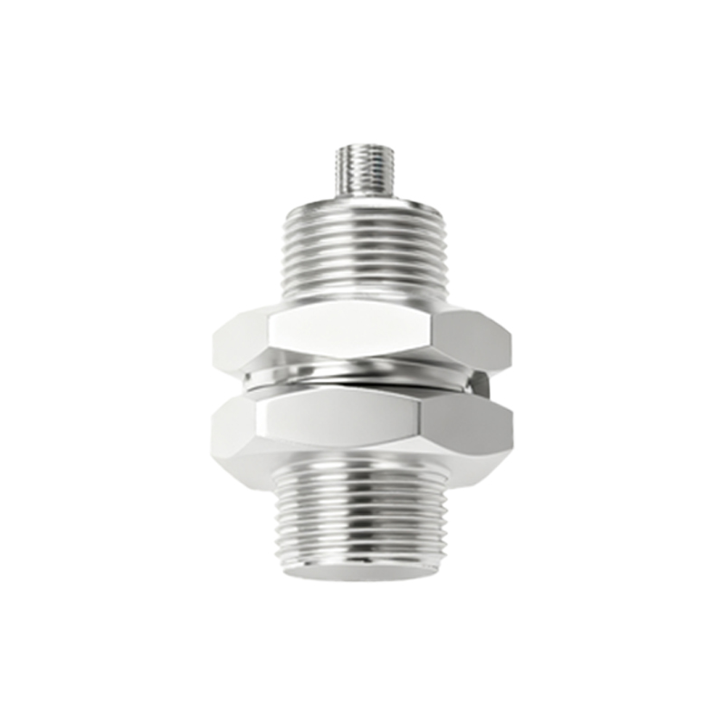
After wiring, power on the system for testing and adjustment. Slowly actuate the valve manually or through the control system. Observe the sensor's indicator LED (if equipped) and monitor the signal status on the PLC. The LED should illuminate steadily when the target is within the sensing range. Fine-tune the sensor's position if the detection is inconsistent. It is crucial to test both end positions (e.g., open and closed) repeatedly to verify reliable switching under normal operating speeds and pressures. Document the final sensor position and settings for future maintenance.
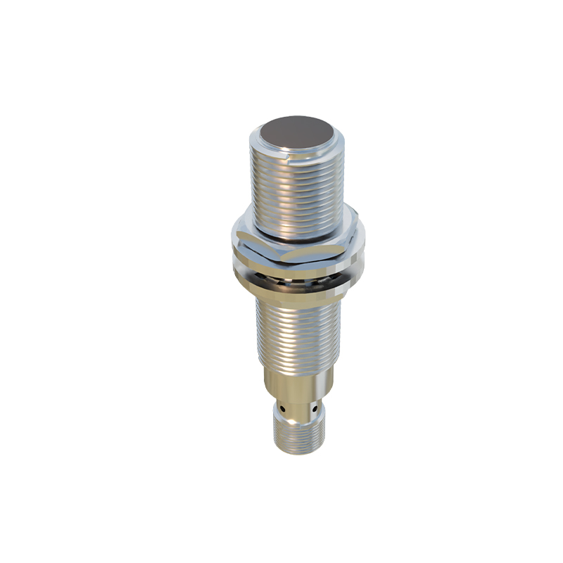
Key considerations for long-term reliability include environmental factors. Ensure the sensor's ingress protection (IP) rating (e.g., IP67) is suitable for the application, protecting against dust and temporary immersion if needed. In high-vibration areas, use vibration-proof locknuts or thread-locking compounds. Regularly inspect the sensor and its mounting during preventive maintenance cycles for any signs of loosening, corrosion, or cable damage. A properly installed proximity sensor not only enhances system diagnostics and safety but also contributes significantly to reducing downtime and improving overall process efficiency in pneumatic valve applications.