Understanding the pinout diagram of a proximity sensor is fundamental for anyone working with industrial automation, robotics, or electronic projects. A proximity sensor detects the presence or absence of an object within a specific range without physical contact, typically using electromagnetic fields, light, or sound. The pinout diagram serves as the essential map, detailing the function of each electrical connection pin on the sensor's housing. Correctly interpreting this diagram is the first critical step toward successful integration and operation.
A standard inductive or capacitive proximity sensor often features a basic three-wire configuration. The pinout commonly includes connections for power supply, ground, and the output signal. For a DC sensor, you will typically find a brown wire (or pin labeled +V or V+) for the positive power supply, usually ranging from 10-30V DC. The blue wire (or pin labeled 0V, COM, or GND) is for the common ground or negative connection. The black wire (or pin labeled OUT, NO, or Signal) carries the switched output signal. When the sensor detects a target, this output pin switches state—either connecting to the power supply voltage (PNP, sourcing) or to ground (NPN, sinking)—to control a load like a PLC input, relay, or indicator lamp.
For more complex sensors, such as analog-output or IO-Link enabled models, the pinout diagram becomes more detailed. A four-wire sensor might have two separate output wires (e.g., one NPN and one PNP) or a dedicated analog output pin (e.g., 0-10V or 4-20mA) alongside the standard power pins. The pinout diagram explicitly labels these, preventing miswiring that could damage the sensor or connected equipment. Always cross-reference the diagram with the sensor's datasheet, as color codes and pin functions can vary between manufacturers like Omron, Sick, or Pepperl+Fuchs.
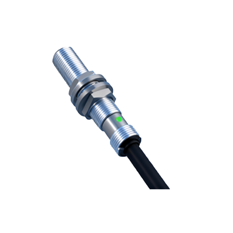
The physical representation of the pinout is equally important. Some sensors have a quick-disconnect connector with clearly molded pin numbers, while barrel-style sensors may have flying leads or terminal screws. The diagram will indicate pin 1, pin 2, etc., corresponding to these physical points. For M8 or M12 circular connectors, which are industry standards, the diagram shows the pin arrangement viewed from the front of the sensor's socket. Misidentifying pin 1 can lead to reversed polarity.
Proper wiring based on the pinout diagram ensures reliable operation and longevity. After connecting power, the output must be linked to the correct interface. For a PNP sensor, the output is connected to the PLC input, and the PLC's common is tied to ground. For an NPN sensor, the PLC common is tied to positive voltage. Ignoring this compatibility detailed in the pinout is a common source of malfunction. Additionally, some diagrams include pins for diagnostic LEDs or teach-in functions for setting sensing ranges.
In summary, the proximity sensor pinout diagram is not merely a suggestion but a mandatory guide. It translates electrical requirements into physical connections, ensuring the sensor receives correct power and communicates its detection signal accurately. Before powering any circuit, consulting the specific model's pinout diagram and accompanying datasheet is the best practice to avoid errors, ensure safety, and achieve optimal performance from your sensing application. Mastering this simple document is a key skill in effective sensor implementation.