In modern industrial automation, precise speed measurement of rotating machinery is critical for process control, efficiency optimization, and predictive maintenance. Programmable Logic Controllers (PLCs) combined with proximity sensors offer a robust, reliable solution for this task. This article explores the principles, implementation, and best practices for using PLCs with proximity sensors to measure rotational speed.
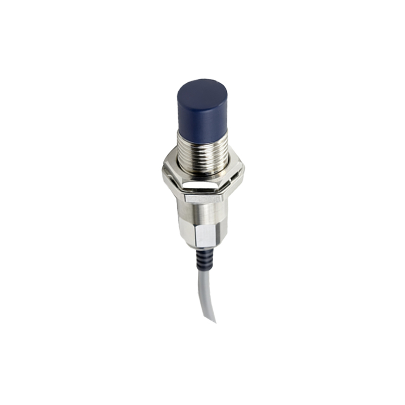
Proximity sensors, particularly inductive or capacitive types, detect the presence or absence of a metallic target without physical contact. When mounted near a rotating shaft equipped with a key, gear tooth, or dedicated trigger point, each pass of the target generates a pulse. The PLC’s high-speed input module captures these pulses, and the controller calculates speed based on the pulse frequency over a defined time interval. For instance, if a shaft has one trigger point and generates 60 pulses per second, the rotational speed is 60 revolutions per second (or 3600 RPM).
The setup involves selecting an appropriate proximity sensor with sufficient sensing range, response time, and environmental durability. Inductive sensors are common for ferrous metals in harsh conditions. Wiring connects the sensor to the PLC’s digital input, with attention to shielding against electrical noise. In the PLC program, a timer or high-speed counter function is configured. Ladder logic or structured text can be used to count pulses within a fixed window—e.g., one second—and compute RPM via arithmetic operations. Advanced PLCs may include dedicated function blocks for frequency measurement, simplifying code development.
Accuracy depends on factors like sensor placement stability, target consistency, and PLC scan time. To minimize error, ensure the trigger point is precisely machined and avoid vibration-induced false triggers. Calibration against a reference tachometer verifies system performance. In applications with multiple trigger points per revolution, divide the pulse count accordingly to obtain correct speed. For variable-speed drives, averaging over multiple cycles smooths out fluctuations.
Integration with broader automation systems enhances functionality. The PLC can compare measured speed against setpoints to control motor drives via analog outputs or communication protocols like Modbus TCP/IP. Alarms for overspeed or underspeed conditions trigger preventive actions, reducing downtime. Data logging of speed trends aids in condition monitoring, identifying wear before failures occur.
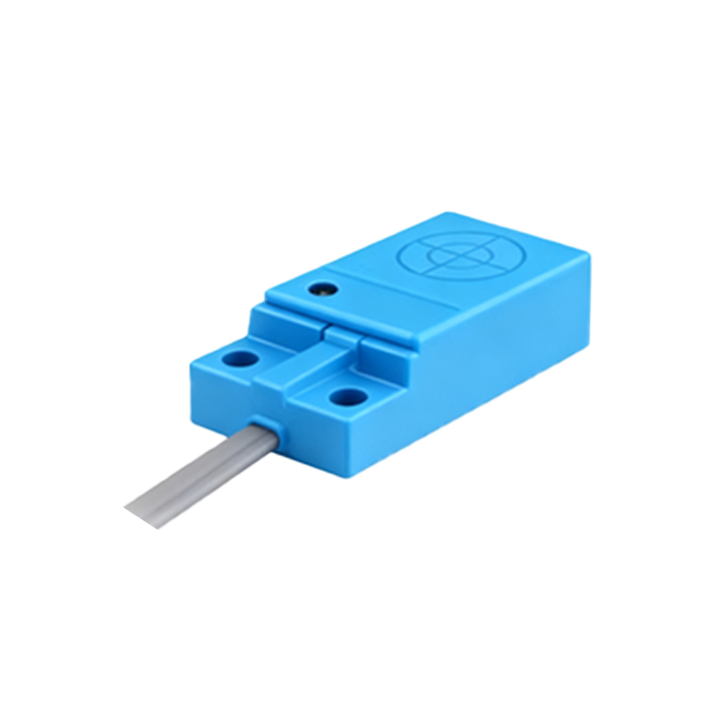
Practical examples include conveyor belt speed monitoring in packaging lines, turbine speed in power generation, and spindle speed in CNC machining. Each application may require tailored sensor selection—e.g., capacitive sensors for non-metallic materials—and PLC programming adjustments. Testing under real operating conditions ensures reliability.
In summary, PLC-based speed measurement with proximity sensors is a versatile, cost-effective method widely adopted in industries. It leverages existing automation infrastructure, requires minimal maintenance, and delivers real-time data for informed decision-making. As Industry 4.0 advances, integrating this approach with IIoT platforms enables remote monitoring and analytics, further boosting operational intelligence. Engineers should prioritize sensor compatibility, noise immunity, and program efficiency to achieve optimal results in diverse industrial environments.
