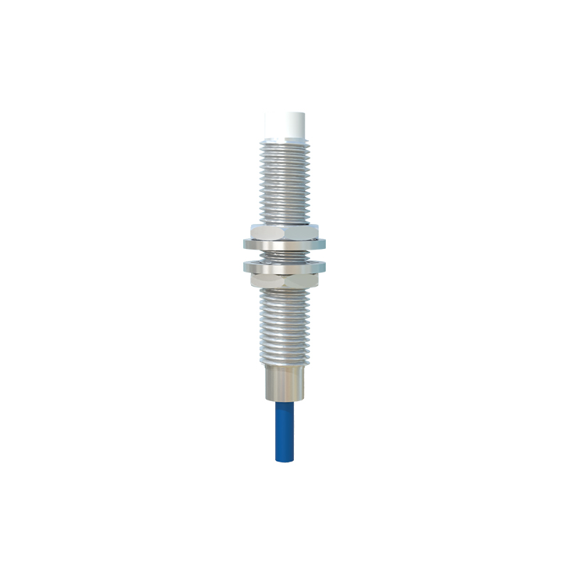
Proximity sensors are essential components in modern automation, robotics, and safety systems, detecting the presence or absence of objects without physical contact. Proper assembly is critical to ensure accurate detection, longevity, and reliability. This guide outlines systematic methods for assembling proximity sensors, covering preparation, installation, wiring, and testing.
Before beginning assembly, gather all necessary tools and materials: the proximity sensor unit, mounting brackets or hardware, appropriate cables (shielded cables are often recommended to reduce electromagnetic interference), wire strippers, screwdrivers, and a multimeter for testing. Always refer to the manufacturer’s datasheet for specific specifications, such as sensing range, voltage requirements, and environmental ratings (e.g., IP67 for dust and water resistance).
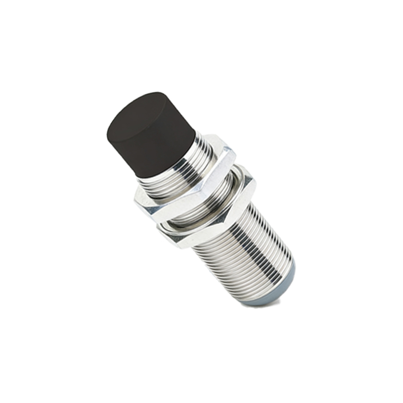
Start by selecting an optimal mounting location. The sensor should be positioned within its specified sensing range, avoiding obstructions or reflective surfaces that could cause false triggers. For inductive sensors (used for metal objects), ensure the target material is compatible; capacitive sensors (for non-metallic materials) may require adjustment for different dielectrics. Mount the sensor securely using provided brackets or hardware, tightening fasteners to prevent vibration-induced misalignment. Avoid over-torquing, which can damage the housing.
Wiring is a crucial step. First, de-energize the power supply to prevent electrical hazards. Strip the cable ends to expose conductors, and connect them according to the sensor’s wiring diagram. Typically, proximity sensors have three wires: brown for positive voltage (e.g., 10-30V DC), blue for negative or ground, and black for the output signal. Some models include a white wire for complementary output or diagnostics. Use crimp connectors or terminal blocks for secure connections, and ensure no loose strands cause short circuits. For harsh environments, consider cable glands or conduits to protect connections from moisture and debris.
After wiring, perform initial checks. Verify that the power supply matches the sensor’s voltage rating using a multimeter. Incorrect voltage can lead to malfunction or permanent damage. Once powered, observe the sensor’s indicator LED (if available); it often lights up when an object is detected. Test the sensing function by introducing a target object within the specified range. Adjust the sensor’s position or sensitivity potentiometer (if equipped) to fine-tune response. For adjustable sensors, use a non-metallic tool to turn the potentiometer, avoiding interference.
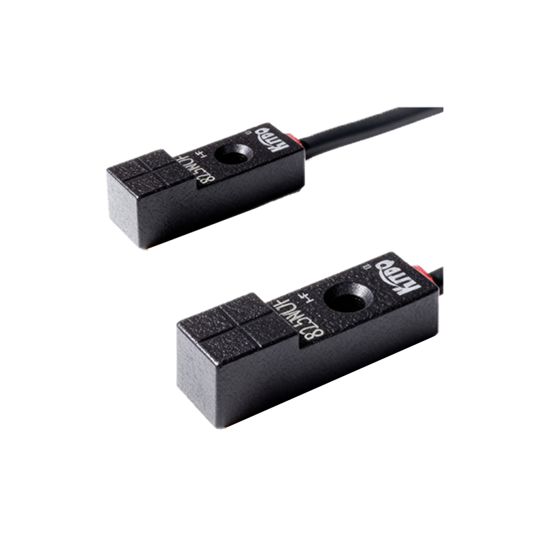
Calibration and testing ensure optimal performance. Measure the response time and repeatability by moving the target in and out of the sensing zone multiple times. The sensor should consistently detect without delay. Check for environmental factors like temperature extremes, humidity, or nearby electrical noise that could affect operation. If issues arise, re-inspect wiring, grounding, and shielding. Proper grounding reduces noise interference, especially in industrial settings with motors or frequency drives.
Finally, secure all components and document the assembly. Label cables and record settings for future maintenance. Regular inspection, such as cleaning the sensor face from dust or oil buildup, prolongs service life. By following these methods, you can achieve reliable proximity sensor assembly, minimizing downtime and enhancing system efficiency.