Accurate temperature measurement is critical in numerous industrial processes, from power generation and chemical processing to HVAC systems and advanced manufacturing. Among the various sensing technologies available, laser water temperature sensors have gained prominence for their non-contact measurement capabilities, high precision, and rapid response times. However, their installation and, crucially, their wiring, require meticulous attention to detail to ensure optimal performance, safety, and data integrity. This guide provides a comprehensive, step-by-step approach to wiring a laser water temperature sensor, tailored for electrical engineers and technicians.
Before initiating any wiring procedure, the first and most critical step is to consult the manufacturer's specific datasheet and installation manual. While general principles apply, specifications for power requirements, signal output types, pin configurations, and communication protocols can vary significantly between models and brands. Assuming compatibility without verification is a primary cause of sensor failure or inaccurate readings.

Understanding the Core Components and Connections
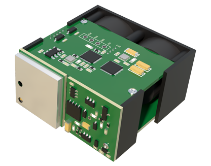
A typical laser water temperature sensor system consists of the sensor head, a control/transmitter unit, and the interconnection cables. The wiring primarily involves the control unit. Common terminals you will encounter include:

* Power Supply (Vcc and GND): This is the lifeline of the sensor. Most industrial units operate on 24 VDC, but 12 VDC or other voltages are possible. Incorrect voltage can permanently damage the electronics. The connection must be made to a clean, stable, and regulated power source. Always observe correct polarity.
* Analog Output (e.g., 4-20 mA, 0-10 V): This is the most common method for transmitting the measured temperature value to a PLC, DCS, or data logger. A 4-20 mA current loop is highly preferred in industrial environments due to its inherent noise immunity and ability to transmit over long distances. Wiring typically involves two terminals: the positive output and the common/return.
* Digital Communication (e.g., RS-485, Modbus RTU, Profibus, Ethernet/IP): For advanced systems requiring bidirectional communication, multi-drop networks, or configuration from a central host, digital interfaces are used. RS-485 with Modbus protocol is extremely common. This requires connecting the A (or D+), B (or D-), and ground/shield wires correctly to create a network. Termination resistors may be required at the ends of the network line.
* Alarm or Relay Outputs: Some sensors provide configurable relay outputs that can trigger an alarm or control an external device (like a valve or pump) when a temperature threshold is exceeded. These are typically dry contact relays (NO/NC) and are wired in series with the alarm circuit's power source.
* Shielding and Grounding: This is non-negotiable for signal integrity. The cable from the sensor head to the control unit and the output signal cables should be shielded. The shield must be grounded at one end only, typically at the control panel ground, to prevent ground loops. Proper grounding of the sensor housing itself is also essential for safety and noise reduction.
Step-by-Step Wiring Procedure
1. Power Down and Lock Out/Tag Out (LOTO): Ensure the entire control panel or system where you are installing the sensor is completely de-energized. Follow your facility's strict LOTO procedures to prevent accidental energization.
2. Mount the Sensor and Control Unit: Physically mount the sensor head at the appropriate measurement point, ensuring a clear line of sight to the water surface or pipe. Mount the control/transmitter unit in a suitable enclosure or DIN rail slot within the control panel.
3. Prepare the Cables: Use the correct cable type as recommended (e.g., shielded twisted-pair for analog/digital signals). Strip the wire ends to the appropriate length for your terminal blocks. For shielded cables, prepare the drain wire and shield braid.
4. Connect Power Wires: Identify the V+ and COM/GND terminals on the control unit. Connect the positive wire from your DC power supply to V+. Connect the negative wire to COM/GND. Double-check the voltage rating.
5. Connect the Analog Output: If using a 4-20 mA output, connect the wire from the positive output terminal (often labeled Iout+) to the positive input terminal of your PLC analog input card. Connect the return wire from the sensor's common to the negative input terminal on the card. Ensure the loop power is sourced correctly (often provided by the PLC card itself or an external supply).
6. Connect Digital Communications (if applicable): For an RS-485 network, connect the 'A' terminal from the sensor to the 'A' line of the network bus. Connect the 'B' terminal to the 'B' line. Connect the signal ground. Set the unique node address via DIP switches or software as per the manual.
7. Handle Shielding: Attach the cable shield drain wire to the dedicated ground terminal or the panel's ground bus bar. Insulate the shield at the opposite end. Ensure the ground connection is secure.
8. Secure and Dress Wires: Neatly route cables away from high-voltage AC power lines and sources of electromagnetic interference (VFDs, motors). Use cable ties and ducting. Loose wires or poor routing are common sources of electrical noise.
9. Power Up and Verify: After a thorough visual inspection of all connections, remove LOTO and apply power. Use a multimeter to verify the power supply voltage at the sensor terminals. Monitor the analog output with a meter while subjecting the sensor to known temperature references (if possible) to validate the reading.
Critical Best Practices and Troubleshooting
* Noise Mitigation: Always use shielded cables. Maintain maximum physical separation between sensor signal lines and power cables carrying AC or high-current DC. Crossing should be at 90-degree angles if unavoidable.
* Environmental Protection: Ensure all conduit entries, cable glands, and enclosure seals are properly rated (e.g., IP67, NEMA 4X) for the installation environment to prevent moisture ingress.
* Initialization: Some digital sensors require a brief initialization period after first power-up. Allow several minutes for the readings to stabilize.
* Common Issues: Erratic readings are often due to poor grounding, incorrect shield handling, or electrical noise. A zero reading may indicate a broken loop or incorrect power. A saturated maximum reading may indicate a wiring short or sensor fault. Systematic verification of each connection against the schematic is the key to resolution.
By adhering to this structured approach—prioritizing safety, meticulously following manufacturer guidelines, and implementing robust wiring practices—engineers can ensure their laser water temperature sensors deliver reliable, accurate, and stable performance, forming a trustworthy foundation for process control and monitoring.