In the high-precision world of industrial laser cutting, sensors are the critical eyes of the operation. They monitor everything from beam alignment and focus position to material presence and gas pressure. A malfunctioning sensor can lead to catastrophic results: poor cut quality, damaged optics, costly machine downtime, and significant material waste. This comprehensive guide, written from an electrical engineering perspective, details the common failure modes of laser cutting sensors and provides a systematic approach to their diagnosis, repair, and preventive maintenance.
The most prevalent sensor types in modern laser cutting systems include capacitive height sensors, optical focus sensors, photodiodes for beam monitoring, and various proximity sensors. Each has a unique function and a corresponding set of common failure points. Capacitive sensors, for instance, are highly sensitive to contamination from cutting fumes and metallic dust. A buildup on the sensor head can cause erratic height control, leading to inconsistent focus and poor edge quality. The primary repair step here is a thorough, gentle cleaning with appropriate solvents and lint-free wipes. For optical sensors, such as those using triangulation or confocal principles, the most frequent issues involve lens fouling or misalignment. A speck of dust on the receiving lens can scatter the laser light, causing the control system to receive incorrect distance data. Careful disassembly, inspection under magnification, and precise cleaning are required. Never use compressed air directly on optical components, as it can drive abrasive particles into coatings.
Diagnosis always begins with the machine's error log and diagnostic software. Modern CNC controllers provide detailed fault codes that can pinpoint the sensor circuit involved. The next step is a visual inspection of the sensor head, its cabling, and the connector. Look for physical damage, discoloration from heat, or signs of coolant ingress. Intermittent faults are often traced to damaged cabling in high-flex areas or loose connectors. A multimeter is your first tool for electrical verification. Check for the correct supply voltage at the sensor connector. For analog output sensors, measure the output signal while manually triggering the sensor; compare the reading to the manufacturer's specifications. For digital sensors, a logic probe or oscilloscope is necessary to verify the integrity of the communication pulse.
Many sensor failures are not within the sensing element itself but in the supporting circuitry. The pre-amplifier board, often located near the sensor head, is susceptible to thermal stress and vibration. Components like operational amplifiers, voltage regulators, and filtering capacitors can degrade. A systematic approach involves checking for burnt components, cold solder joints, or cracked traces. Replacing a swollen electrolytic capacitor can often restore a sensor to full function. For photodiode-based beam monitoring sensors, the diode itself can be damaged by back-reflected laser light. Testing requires a calibrated light source and careful measurement of the photocurrent. In many cases, replacement of the photodiode assembly is more cost-effective than attempting a repair.
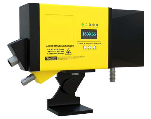
After any repair, calibration is non-negotiable. A repaired capacitive height sensor must be recalibrated using the manufacturer's gauge set to ensure its distance-to-voltage curve is accurate. An optical focus sensor requires a calibration routine that involves scanning a known reference surface. Skipping this step will result in process inaccuracies that negate the repair. Furthermore, implement a robust preventive maintenance schedule. This includes weekly cleaning of sensor optics with approved materials, monthly inspection of all cable harnesses for wear, and quarterly verification of sensor output signals against a master reference. Keeping a log of sensor performance trends can help predict failures before they occur.
Ultimately, successful sensor repair hinges on a methodical process: utilize diagnostic tools, understand the sensor's operating principle, inspect mechanically and electrically, repair or replace faulty sub-assemblies, and always recalibrate. Investing in proper training for maintenance technicians and maintaining a stock of critical sensor spares are the best strategies to minimize unplanned downtime and ensure the relentless precision demanded by today's laser cutting applications.