In the realm of industrial automation and control systems, proximity switches are indispensable components for non-contact detection of metallic objects. At the heart of many inductive proximity sensors lies a critical electronic circuit: the LC oscillator. This article delves into the operational principles, design considerations, and practical implications of the LC oscillator circuit within the context of proximity sensing technology.
Fundamentally, an inductive proximity sensor operates by generating an electromagnetic field. The core component responsible for this is a coil, which, when combined with a capacitor, forms an LC tank circuit—the oscillator's resonant element. When powered, this LC circuit oscillates at its natural resonant frequency, determined by the formula f = 1 / (2π√LC), where L is the inductance of the coil and C is the capacitance. In a stable state with no target present, the oscillator maintains constant amplitude oscillations.
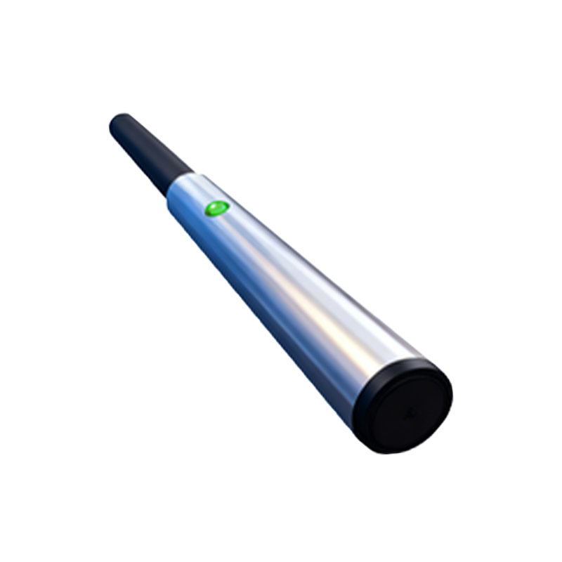
The sensing mechanism is elegantly based on the principles of electromagnetic induction. When a metallic target enters the sensor's active electromagnetic field, eddy currents are induced on the surface of the target. These eddy currents draw energy from the oscillating circuit, effectively acting as a power loss. This loss manifests as an increase in the "load" on the coil, which in turn causes a change in the effective inductance (L) of the coil. This change in inductance disrupts the carefully balanced conditions of the LC tank circuit.
The key to detection lies in monitoring the oscillator's amplitude. As the target approaches, the energy loss increases, causing the amplitude of the oscillations to decrease. The sensor's internal evaluation circuit continuously monitors this amplitude. A threshold circuit or amplitude detector is employed to compare the current oscillation level against a predefined reference value. Once the amplitude drops below this threshold—indicating a target is within the specified sensing range—the output stage of the sensor is triggered. This output typically switches a solid-state transistor (PNP or NPN) or a relay, sending a signal to the programmable logic controller (PLC) or other control system.
Several critical factors influence the performance and design of this LC oscillator circuit. First is the choice of operating frequency. Higher frequencies generally allow for the detection of smaller objects and can provide faster response times, but they may have reduced sensing ranges and be more susceptible to noise. Common frequencies range from 100 kHz to several megahertz. The quality factor (Q-factor) of the LC tank is another vital parameter. A high Q-factor indicates a sharp resonance peak, leading to greater amplitude change for a given inductance shift, thereby enhancing sensitivity. However, an excessively high Q can make the circuit unstable and prone to drifting.
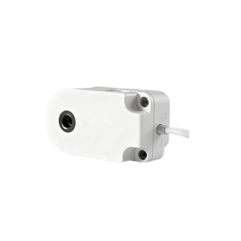
Component selection is paramount. The coil is often wound on a ferrite core to concentrate the magnetic field and increase inductance, extending the sensing range. The capacitor must be stable with temperature and time; often, ceramic or silver-mica capacitors are preferred for their stability. The active sustaining circuitry, usually built around a transistor or an operational amplifier, must provide just enough gain to overcome circuit losses and maintain oscillations without being overdriven, which would reduce sensitivity.
Environmental considerations are also crucial in industrial settings. Temperature variations can affect both the coil's inductance and the capacitor's value, potentially shifting the resonant frequency. High-quality sensors incorporate temperature compensation circuits or use components with complementary temperature coefficients to mitigate this drift. Furthermore, electrical noise from motors, variable frequency drives, or other sensors can interfere with the oscillator. Shielding of the coil, proper grounding, and sometimes frequency modulation techniques are employed to ensure reliable operation in electrically noisy environments.
In advanced proximity sensors, the LC oscillator's frequency shift is sometimes monitored instead of, or in addition to, the amplitude change. A frequency-to-voltage converter circuit can translate the small frequency change caused by the target's presence into a usable signal. This method can offer advantages in certain applications requiring analog output or superior noise immunity.
In conclusion, the LC oscillator circuit is the fundamental engine of the inductive proximity switch. Its ability to translate a physical phenomenon—the disturbance of a magnetic field by a metallic object—into a clear, measurable electrical signal is a cornerstone of modern industrial automation. Understanding its design, from the resonant LC tank to the supporting detection electronics, is essential for engineers selecting, integrating, and troubleshooting these ubiquitous sensors. As technology advances, the core principle remains, while integration and signal processing techniques continue to evolve, enabling smarter, more robust, and more precise proximity detection solutions.