In industrial automation and control systems, photoelectric sensor proximity switches are indispensable components for detecting the presence, absence, or position of objects without physical contact. Their reliable operation hinges significantly on the proper selection and application of a general power supply. This article delves into the key aspects of powering these sensors, ensuring optimal performance and longevity in diverse operational environments.
Photoelectric sensors typically operate on direct current (DC) power supplies. The most common voltage ratings are 12-24 VDC, aligning with standard industrial control voltages. It is crucial to consult the sensor's datasheet or nameplate for the exact voltage range, as deviations can lead to malfunction or permanent damage. A stable, regulated DC power supply is recommended to minimize voltage fluctuations that could affect sensing accuracy and response time. Ripple voltage, a residual periodic variation from the power supply, should be kept within the sensor's specified tolerance, usually below 10% of the nominal voltage, to prevent erratic behavior.
Wiring and polarity are fundamental considerations. Most photoelectric sensors utilize a three-wire configuration: brown wire for positive DC supply (+V), blue wire for negative/common (0V), and black wire for the output signal. Some models may have a white wire for complementary output or other functions. Adhering to correct polarity is non-negotiable; reverse connection can instantly destroy the internal circuitry. For two-wire DC sensors, which are simpler but have inherent voltage drop, careful calculation of the load current is necessary to ensure sufficient operating voltage remains at the sensor.
The choice between a switching (SMPS) or linear power supply depends on the application's demands. Switching power supplies are efficient, compact, and suitable for most general applications. However, in environments with sensitive electronic equipment, a linear power supply, which generates less electrical noise, might be preferable to prevent electromagnetic interference (EMI) from affecting the sensor's signal integrity. Regardless of type, the power supply's current rating must exceed the total current draw of all connected sensors and their loads. Always include a safety margin of at least 20-30% to account for inrush currents and potential future expansions.
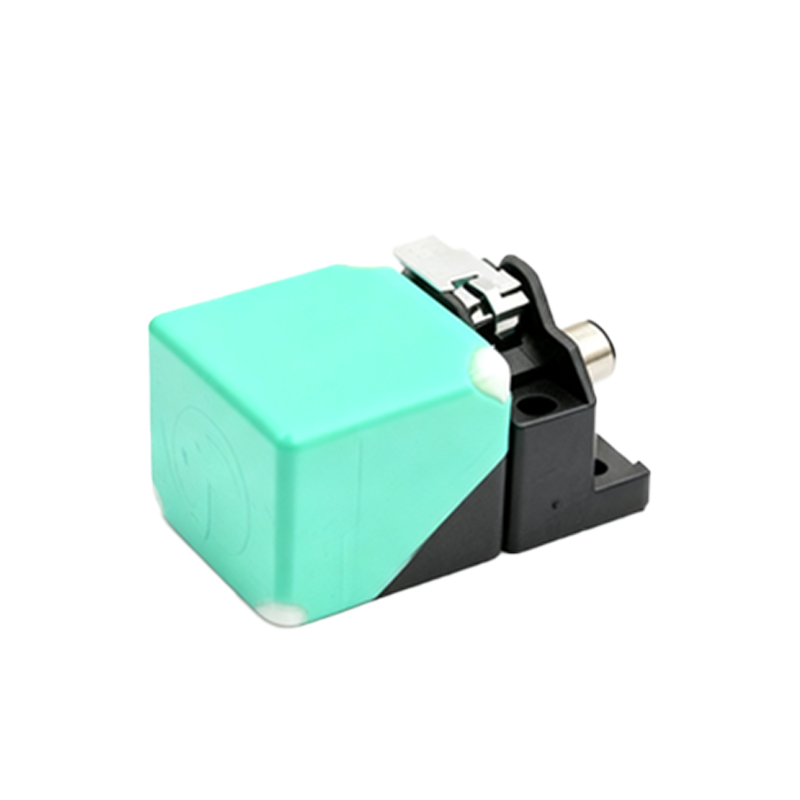
Protection circuits are vital for durability. Incorporating fuses or circuit breakers on the supply line safeguards against overcurrent conditions. For sensors operating in areas with inductive loads (e.g., relays, solenoids), using flyback diodes or transient voltage suppressors is essential to clamp voltage spikes that could feedback into the power line and damage the sensor. In harsh environments with significant electrical noise, employing a dedicated, isolated power supply for the sensor system can dramatically enhance noise immunity.
For systems with multiple sensors, a centralized, well-filtered power distribution module is often more reliable than daisy-chaining power from one sensor to another. This approach ensures each sensor receives consistent voltage, minimizing ground loop issues and voltage drops across the chain. Regular maintenance, including checking power connections for corrosion and tightness, and monitoring supply voltage with a multimeter, preempts many common failure modes.
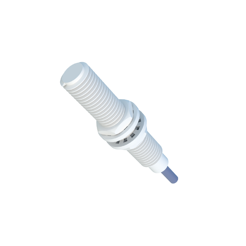
In summary, powering photoelectric sensor proximity switches correctly is a cornerstone of system reliability. By selecting a stable DC supply within the specified range, adhering to proper wiring practices, implementing necessary protections, and planning for the system's total current demand, engineers can ensure these critical sensors perform accurately and consistently, forming a robust backbone for automated processes.