Laser sensors are integral components in modern industrial automation, offering high precision, reliability, and non-contact measurement capabilities. A comprehensive understanding of laser sensor circuit diagrams is essential for engineers and technicians involved in system design, installation, and maintenance. This article delves into the key elements of these diagrams, explaining their functionality and practical applications in industrial settings.
At the core of a laser sensor circuit is the laser diode, which emits a focused beam of light. The circuit diagram typically illustrates the power supply section that provides stable voltage to the laser diode, often incorporating regulators and protection components like resistors and capacitors to prevent voltage spikes. Adjacent to this, the driver circuit controls the laser's output, ensuring consistent intensity and modulation for accurate sensing. This section may include transistors or integrated circuits (ICs) designed for laser driving, with feedback loops to maintain stability.
The receiver portion of the circuit is equally critical. It consists of a photodetector, such as a photodiode or phototransistor, which captures the reflected laser beam. The diagram shows how this component connects to amplification stages, where operational amplifiers (op-amps) boost the weak electrical signals generated by the photodetector. Signal conditioning circuits follow, often featuring filters to eliminate noise from ambient light or electrical interference, ensuring clean data transmission.
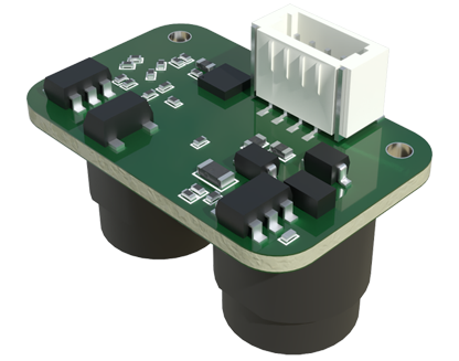
Processing units, like microcontrollers or digital signal processors (DSPs), are depicted in the circuit diagram to handle the conditioned signals. These units interpret the data to determine parameters such as distance, presence, or thickness, based on time-of-flight or triangulation principles. Output interfaces, including analog outputs (e.g., 4-20 mA) or digital communication protocols (e.g., IO-Link, Ethernet/IP), are also detailed, showing how the sensor integrates with broader control systems like PLCs or HMIs.

Safety features are prominently highlighted in laser sensor circuit diagrams. These may include current-limiting resistors to protect the laser diode from overheating, optical isolators to prevent electrical hazards, and compliance markings for standards such as IEC 60825-1, which governs laser safety. Engineers must adhere to these guidelines to ensure safe operation in industrial environments.
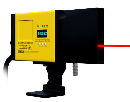
In practice, interpreting these diagrams requires attention to component specifications, such as voltage ratings and signal thresholds. For instance, a typical diagram might label connections for power (Vcc and GND), output signals, and adjustment pins for sensitivity or response time. Troubleshooting common issues, like signal drift or output failure, involves checking these connections and testing individual circuit blocks with multimeters or oscilloscopes.
Applications of laser sensors span various industries, from automotive manufacturing, where they monitor assembly line gaps, to packaging, where they detect label positions. The circuit diagram serves as a roadmap for customization, allowing engineers to modify parameters like beam divergence or response speed to suit specific tasks. As Industry 4.0 advances, integrating laser sensors with IoT platforms further emphasizes the need for clear, accurate diagrams to facilitate smart factory implementations.
In summary, laser sensor circuit diagrams are vital tools for optimizing industrial processes. By mastering their layout and components, professionals can enhance system performance, ensure safety, and drive innovation in automation. Continuous learning about emerging technologies, such as miniaturized circuits or AI-enhanced sensors, will further empower engineers to leverage these diagrams for future-ready solutions.