Proper installation and wiring of crane proximity switch sensors are critical for ensuring safe and efficient operation of overhead cranes, hoists, and other material handling equipment. These non-contact sensors detect the presence of metallic objects, such as crane hooks or trolleys, and are essential for preventing collisions, enabling automatic positioning, and triggering safety limits. Incorrect wiring can lead to sensor failure, false triggers, or even safety hazards. This guide provides a comprehensive, step-by-step approach to wiring these sensors, adhering to standard industrial practices and electrical safety protocols.
Before beginning any wiring work, the foremost rule is safety. Always lock out and tag out (LOTO) the main power supply to the crane control circuit. Verify the absence of voltage using a properly rated multimeter. Ensure you have the correct sensor for your application (inductive, capacitive, or magnetic), with the appropriate sensing range, voltage rating (e.g., 10-30V DC, 20-250V AC/DC), and output type (PNP, NPN, NO, NC). Gather necessary tools: wire strippers, crimping tools, appropriate gauge wires (typically shielded cable for noise immunity), conduit, and the sensor's datasheet or wiring diagram.
Most industrial proximity switches for cranes have three or four wires. The standard color coding for DC sensors is: Brown for positive supply (+V), Blue for negative supply (0V or common), and Black for the output signal. A White wire, if present, is often a complementary output or diagnostic line. For AC sensors, typically two wires (Live and Load) are used. ALWAYS CONSULT THE MANUFACTURER'S DOCUMENTATION, as colors can vary.
Here is a detailed wiring procedure for a common 3-wire DC PNP (sourcing) sensor:
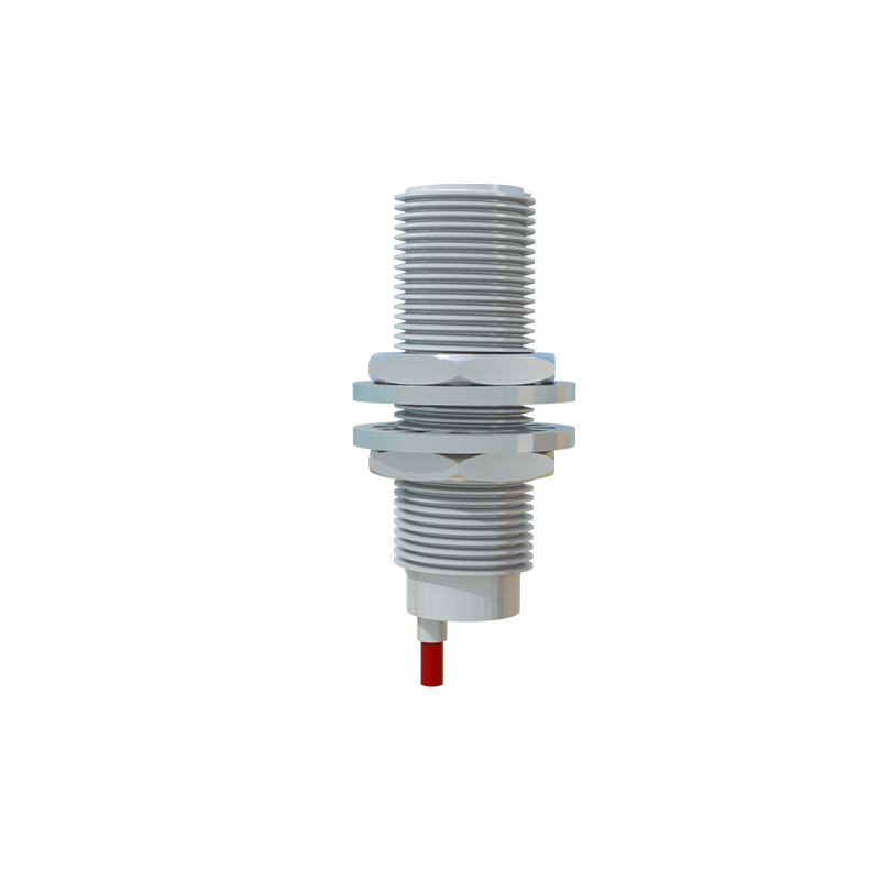
1. Power Supply Connection: Identify a suitable, stable DC power source that matches the sensor's voltage specification (commonly 24V DC in industrial panels). Connect the Brown wire (+V) from the sensor to the positive terminal of the power supply. Connect the Blue wire (0V) from the sensor to the negative terminal of the power supply. Use fuses or circuit breakers as per the control panel design to protect the circuit.
2. Output Signal Connection: The Black wire is the switched output. In a PNP sensor, this wire supplies positive voltage when a target is detected. This output must be connected to the input of your control device, such as a Programmable Logic Controller (PLC) input module, a relay coil, or a pilot light.
Connecting to a PLC Digital Input: Connect the sensor's Black wire to the designated PLC input terminal (e.g., I0.0). The corresponding common terminal of that PLC input module must be connected to the power supply's negative (0V). This completes the circuit. When the sensor activates, it sends +24V to the PLC input, signaling a "TRUE" or "1" state.
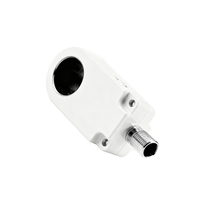
Connecting to a Relay: Connect the Black wire to one side of the relay coil. Connect the other side of the relay coil to the power supply negative (0V). A flyback diode across the relay coil is recommended to suppress voltage spikes.
3. Shielding and Noise Protection: For long cable runs or electrically noisy environments (common near VFDs and large motors), use shielded cable. Connect the cable's shield braid to a functional earth ground at the control panel end only. Do not connect the shield at both ends to avoid ground loops. Run sensor wires separately from high-voltage power lines.
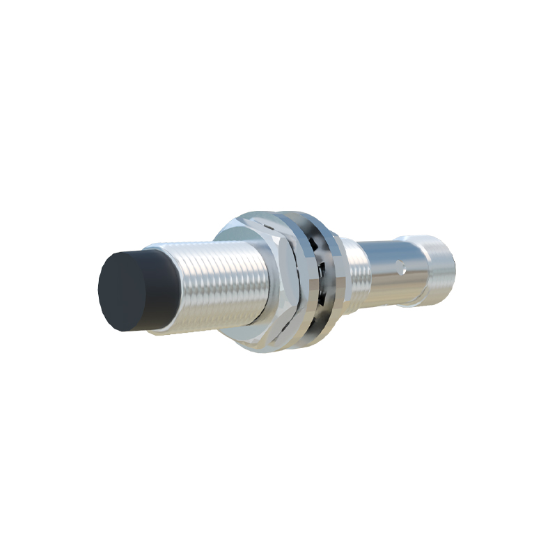
4. Sensor Mounting and Adjustment: Physically mount the sensor securely on the crane bridge, trolley, or hoist, ensuring correct alignment and the specified gap (usually 2-5mm) between the sensor face and the metallic target (e.g., a limit dog or the hook block). Adjust the position so the target reliably enters and leaves the sensing field.
5. Testing and Commissioning: After wiring, restore power cautiously. Use a non-metallic tool to bring a target (like a wrench) near the sensor's sensing face. Observe the sensor's LED indicator (if equipped) and verify the correct state change on the PLC input indicator or the actuation of the connected relay. Test the sensor's operation at the extremes of its mechanical travel to ensure reliable detection without false triggers.
For NPN (sinking) sensors, the wiring logic is reversed. The Black output wire sinks current to negative (0V) when active. Here, the PLC input common terminal would be connected to positive (+V), and the sensor's Black wire connects to the PLC input. The Blue wire still goes to 0V, and