In the field of industrial automation and electrical engineering, the ability to accurately create and interpret assembly diagrams is a fundamental skill. Proximity sensors, as non-contact detection devices, are ubiquitous components in control systems. This guide provides a detailed, step-by-step methodology for drawing a professional proximity sensor assembly diagram, adhering to standard engineering drafting practices and conventions.
1. Preliminary Information Gathering and Planning
Before putting pen to paper or opening CAD software, thorough preparation is essential. Begin by collecting all relevant technical data for the specific proximity sensor model. This includes the manufacturer's datasheet, dimensional drawings, mechanical specifications, and electrical connection details. Identify the sensor type: inductive, capacitive, or photoelectric. Determine the exact housing style (e.g., cylindrical barrel, rectangular, ring-shaped) and the connection type (e.g., pre-wired cable, quick-disconnect plug, terminal block). Clarify the diagram's purpose. Is it for installation guidance, maintenance documentation, or integration into a larger system schematic? Defining the scope ensures the diagram contains the appropriate level of detail.
2. Selecting Tools and Establishing Standards
Modern engineering diagrams are predominantly created using Computer-Aided Design (CAD) software. Tools like AutoCAD Electrical, SolidWorks, EPLAN, or even standard AutoCAD with appropriate symbol libraries are industry standards. Establish your drafting standards upfront:
Layers: Create separate layers for different elements: outline, internal components, dimensions, labels, electrical connections.
Line Weights: Use thick lines for the main housing outline, medium lines for internal parts, and thin lines for hidden details, cross-sections, or centerlines.
Text Style: Choose a clear, sans-serif font (e.g., Arial, ISO font). Maintain consistent text height for dimensions, labels, and notes.
3. Drawing the Mechanical Outline and Key Features
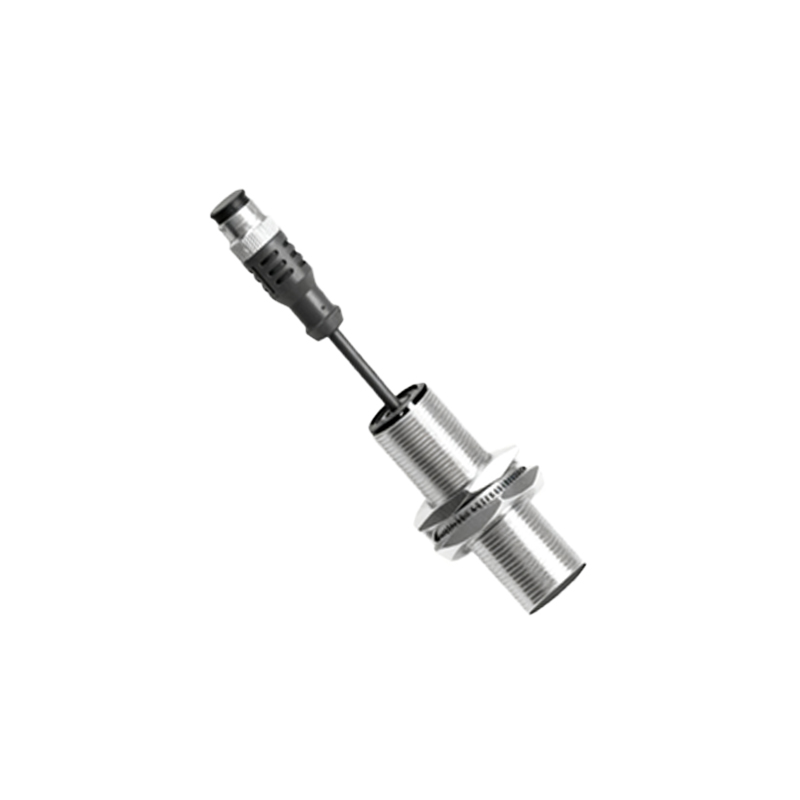
Start by constructing the primary external housing of the sensor to scale. For a common cylindrical inductive sensor, this involves drawing the main barrel body, the sensing face, and the mounting threads or bracket. Accurately represent key mechanical features:
Draw the precise shape and size of the sensing face, often marked on the housing.
Illustrate mounting details: hex nut dimensions for barrel sensors, bolt holes for rectangular brackets.
Include the cable entry point or connector housing. For pre-wired versions, show the cable strain relief gland.
If the diagram includes a cross-sectional view, carefully depict the internal threading, sealing rings (O-rings), and the separation between the sensing coil assembly and the housing.
4. Detailing Internal Components (Simplified Representation)
A detailed assembly diagram often includes a simplified internal view to show key functional parts without revealing proprietary design. This is typically a schematic representation, not a photorealistic rendering.
For an inductive sensor, draw a simple coil symbol within the housing, positioned behind the sensing face.
Represent the oscillator and detection circuit as a small, labeled block diagram inside the housing.
Show the connection between the internal electronics and the output terminals or cable leads.
Clearly indicate the location of any status LED (Light Emitting Diode).
5. Defining Electrical Connections and Terminals
This is a critical part of the diagram. Clearly label all electrical connection points according to the sensor's wiring scheme.
For a 3-wire DC sensor, label the terminals or cable leads as: +V (Brown/Brown+Blue), 0V (Blue), and Output (Black). For PNP (sourcing) and NPN (sinking) types, the output symbol (a switch) should be drawn connected appropriately to the supply lines.
For 2-wire AC/DC sensors, label the two connections clearly.
Use standard electrical symbols for the output switch (normally open (NO) or normally closed (NC)) and the power supply connections.
If a quick-disconnect plug is used, draw its mating connector separately and label the pin assignments (e.g., Pin 1: +V, Pin 2: Output, Pin 3: 0V).
6. Adding Dimensions, Labels, and Annotations
A diagram is incomplete without precise dimensions and clear annotations.
Add all critical dimensions: overall length and diameter, mounting thread size (e.g., M18x1), sensing distance (Sn), and distances to key features. Use extension lines, dimension lines, and arrows.
Label every major part: "Housing (Stainless Steel)", "Sensing Face", "Mounting Nut", "Cable Gland", "LED Indicator", "Internal Oscillator Coil", "Output Transistor Block".
Include a title block with the sensor