Inductive proximity sensors are fundamental components in industrial automation, offering non-contact detection of metallic objects. A critical aspect of their installation and functionality lies in understanding their pin configurations, which vary based on design, output type, and wiring standards. Typically, these sensors feature three or four pins, each serving a distinct purpose in the circuit.
The most common configuration is the three-wire DC sensor, which includes pins for power supply, ground, and output signal. The power supply pin (often labeled V+ or brown wire per IEC standards) connects to the positive DC voltage, usually ranging from 10-30 VDC. The ground pin (labeled 0V or blue wire) completes the circuit, while the output pin (black wire) provides the switching signal—either normally open (NO) or normally closed (NC)—to control external devices like PLCs or relays. For sensors with complementary outputs, a fourth pin (white wire) may be present to deliver an inverted signal, allowing for simultaneous NO and NC functionality. This is particularly useful in safety circuits or complex control logic.
Wiring patterns also differ between sinking (NPN) and sourcing (PNP) output types. In a sinking sensor, the output pin connects the load to ground when activated, common in Asian-market designs. Conversely, a sourcing sensor supplies positive voltage to the load, prevalent in Europe and North America. Misinterpreting these can lead to circuit damage or malfunction. Additionally, some sensors incorporate pin configurations for diagnostics, such as short-circuit protection or LED status indicators, which are integrated into the housing but may share electrical connections with the main pins.
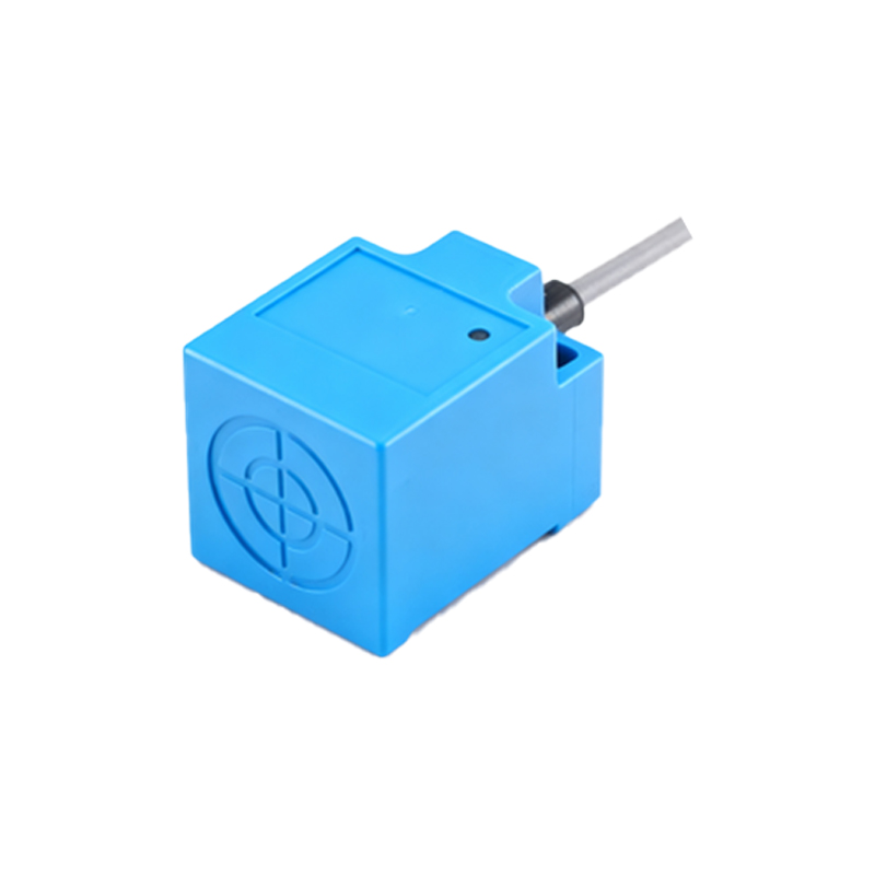
Shielded and unshielded sensor designs further influence pin layouts. Shielded sensors have a metallic front face that concentrates the electromagnetic field, allowing flush mounting in metal. Their pins are often insulated to prevent interference. Unshielded sensors, with an extended sensing range, may include auxiliary pins for calibration or sensitivity adjustment in programmable models. Engineers must consult datasheets to verify pin assignments, as color codes can vary by manufacturer despite IEC attempts at standardization.
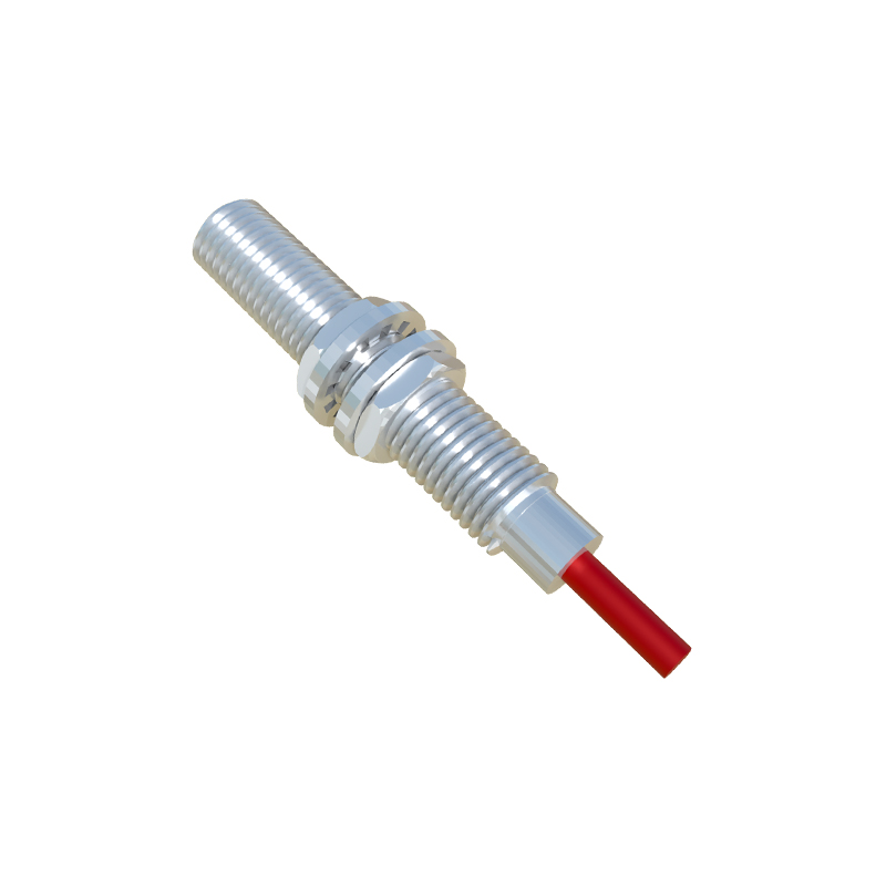
Proper connection ensures reliable operation in harsh environments with vibration, temperature fluctuations, or electromagnetic noise. For instance, using twisted-pair cables and grounding the shield pin (if available) reduces interference. Incorrect wiring—such as reversing polarity or overloading the output—can cause permanent failure. As Industry 4.0 advances, smart sensors with IO-Link capabilities are emerging, featuring additional pins for digital communication that enable parameter setting and condition monitoring without physical adjustments.
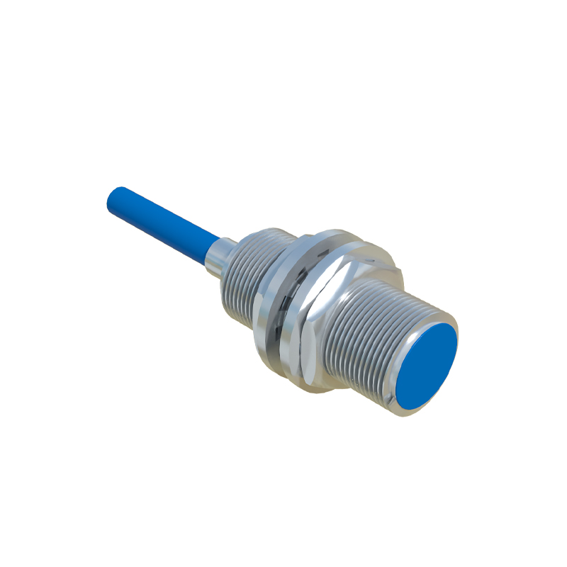
In summary, mastering inductive proximity sensor pin configurations is essential for seamless integration into automated systems. By recognizing output types, adhering to wiring standards, and leveraging diagnostic features, engineers can optimize performance, minimize downtime, and enhance safety across applications from conveyor belts to robotic arms.