In the realm of industrial automation and control systems, proximity sensors are indispensable components for detecting the presence or absence of an object without physical contact. Among the various types, 3-wire DC sensors are most prevalent, primarily categorized into two output configurations: NPN and PNP. For engineers, technicians, and system integrators, grasping the fundamental distinction between these two types is crucial for correct wiring, system compatibility, and reliable operation. This article delves into the core differences, operational principles, and practical application considerations for NPN and PNP proximity sensors.
At the heart of the difference lies the type of bipolar junction transistor (BJT) used in the sensor's output switching circuit. This internal semiconductor design dictates how the sensor interfaces with the load and the power supply, fundamentally defining its sinking or sourcing behavior.
An NPN proximity sensor utilizes an NPN transistor for its output. In this configuration, the emitter of the transistor is connected to the negative voltage supply (0V or common). When the sensor detects a target, the internal transistor switches "ON," allowing current to flow from the load, through the sensor's output wire (typically the black wire), and to the negative supply (ground). In simpler terms, the NPN output provides a path to ground for the load current. This is known as a "sinking" output. The load (e.g., a PLC input module, relay coil) must be connected between the positive supply voltage (+V) and the sensor's output terminal. When active, the sensor "sinks" the current to complete the circuit to ground.
Conversely, a PNP proximity sensor employs a PNP transistor. Here, the emitter is connected to the positive voltage supply (+V). Upon detection, the transistor switches "ON," allowing current to flow from the positive supply, through the sensor's output wire, and to the load. Thus, the PNP output provides a positive voltage source to the load. This is termed a "sourcing" output. The load must be connected between the sensor's output terminal and the negative supply (0V). When active, the sensor "sources" the current from the positive supply to the load.
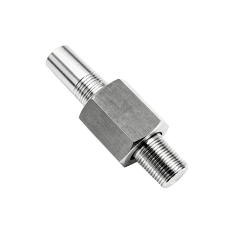
A practical and memorable way to distinguish them is: "PNP = Positive-switched." A PNP sensor switches the positive voltage to the load. "NPN = Negative-switched." An NPN sensor switches the negative path (ground) to the load.
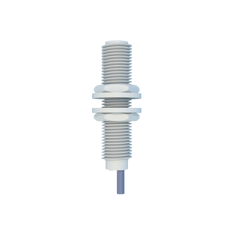
The choice between NPN and PNP is not about one being superior to the other in performance; both offer similar sensing ranges, response times, and housing styles. The selection is predominantly dictated by the electrical design of the control system it must interface with, which is often influenced by regional conventions and PLC input card design.
In many European and Asian countries, PNP (sourcing) sensors are the de facto standard. Control systems are often designed with PLC input modules that require a positive voltage signal. Here, a PNP sensor's output wire connects directly to the PLC input, which is internally connected to common (0V). When the sensor activates, it sources +24V to the PLC input, registering a logic HIGH or "1."
In contrast, NPN (sinking) sensors are historically more common in Japan and in many applications in North America. In these systems, PLC input modules are often designed to be "sinking" themselves. They internally provide a positive voltage to the input terminal. An NPN sensor's output wire connects to the PLC input. When active, the sensor sinks this current to ground, pulling the input voltage low and registering a logic LOW or "0," though the PLC programming is typically configured to interpret this as a true condition.
A critical consideration is ensuring compatibility. Connecting a PNP sensor to a sinking-type PLC input, or an NPN sensor to a sourcing-type input, will result in a non-functional circuit and potential confusion. Modern PLCs often offer universal input cards that can be configured for either sinking or sourcing operation, providing greater flexibility.
When wiring, always refer to the sensor's datasheet, which will clearly label the wire functions: Brown for +V (L+), Blue for 0V (L- or common), and Black (sometimes White) for the output signal. The wiring diagram will illustrate the correct connection for the chosen type.
In summary, the dichotomy between NPN and PNP proximity sensors is a foundational concept in industrial electrical design. NPN sensors act as sinking switches, connecting the load to ground. PNP sensors act as sourcing switches, providing positive voltage to the load. The correct selection ensures seamless integration, prevents wiring errors, and guarantees the robust and fail-safe operation of automated machinery. Understanding this distinction is a fundamental skill for any professional working with sensor-based control systems.
SEO