Metal proximity sensors are fundamental components in industrial automation, enabling non-contact detection of metallic objects. Their operation relies on electromagnetic principles, primarily through inductive sensing technology. This article delves into the schematic design and working principles of these essential devices, providing a detailed analysis for engineers and technicians in the electrical and automation fields.
At the core of a metal proximity sensor is an oscillator circuit that generates a high-frequency electromagnetic field. The schematic typically includes an LC tank circuit, where an inductor (coil) and capacitor resonate at a specific frequency. When a metallic object enters this field, eddy currents are induced on the metal's surface, causing a change in the oscillator's amplitude or frequency. This alteration is detected by a threshold circuit, which triggers an output signal—usually through a solid-state switch like a transistor or an integrated circuit.
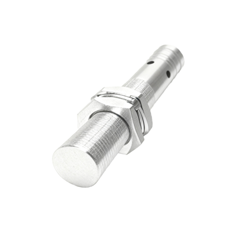
A standard schematic diagram comprises several key sections: the oscillator, demodulator, amplifier, and output stage. The oscillator, often built around a Colpitts or Hartley configuration, produces the sensing field. The demodulator converts AC signals to DC, while the amplifier boosts the detected change to a usable level. The output stage interfaces with control systems, commonly providing a PNP or NPN transistor output, or a relay contact in some models. Additional components, such as voltage regulators, protection diodes, and filtering capacitors, ensure stable operation in noisy industrial environments.
Design considerations include sensing range, which depends on coil geometry and oscillator power, and material factors—ferrous metals like iron typically yield longer detection distances than non-ferrous metals like aluminum due to higher permeability. Shielding is another critical aspect; shielded sensors have a narrower field, reducing side detection, while unshielded types offer extended range but are more susceptible to interference. Schematics also incorporate hysteresis circuits to prevent output chatter when an object is at the detection boundary.
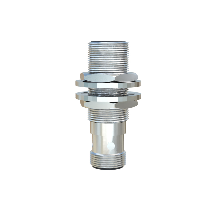
In practice, engineers must interpret schematics to troubleshoot issues like false triggering or reduced range. Common faults involve damaged oscillator components, faulty output transistors, or power supply problems. Understanding the schematic allows for precise diagnostics, such as checking capacitor values in the LC circuit or testing diode integrity in the protection network.
Modern advancements include analog sensors with proportional output and digital variants with programmable features, but the core schematic principles remain consistent. These sensors are widely used in applications like conveyor systems, machine safety, and position sensing, where reliability is paramount. By mastering the schematic details, professionals can optimize sensor selection, integration, and maintenance, enhancing system efficiency and uptime.
In summary, metal proximity sensor schematics reveal a sophisticated yet elegant design that translates electromagnetic interactions into actionable signals. With a solid grasp of these diagrams, engineers can leverage these devices effectively across diverse industrial settings, ensuring robust and responsive automation solutions.