In industrial automation and control systems, proximity switches are indispensable components for non-contact detection of objects. A common yet perplexing issue encountered by maintenance engineers and technicians is the scenario where the sensor's indicator light is illuminated, suggesting power and basic functionality, but no output signal is being generated or received by the PLC, controller, or downstream device. This "light on, no signal" condition can lead to production stoppages, sequencing errors, and significant downtime if not diagnosed efficiently. This article delves into the root causes, systematic troubleshooting methodologies, and practical solutions from an engineering perspective.
The illuminated LED on a proximity sensor typically signifies that the device is powered and its oscillator circuit is active. In an inductive proximity sensor, for instance, this light often indicates that the electromagnetic field is present. However, the output stage—be it PNP (sourcing), NPN (sinking), or a solid-state relay—is what actually switches to provide the signal. A disconnect between the indicator and the output is the core of the problem.
A structured, top-down approach is crucial for effective troubleshooting. Begin with the most accessible and common points of failure before proceeding to more complex internal diagnostics.
1. Verify Wiring and Power Supply:
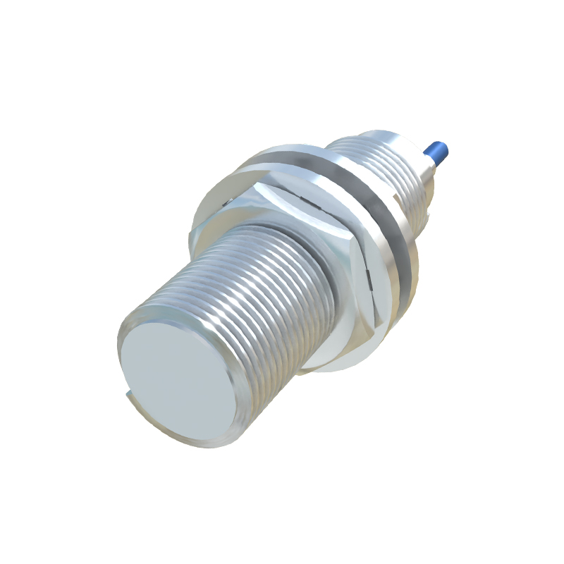
Despite the lit indicator, never assume wiring is perfect. Check for correct voltage polarity and magnitude at the sensor's terminals using a multimeter. A voltage drop due to long cable runs, undersized wires, or a failing power supply might provide enough juice for the LED but not for the output transistor to switch reliably. Ensure the sensor's voltage rating matches the supply (e.g., 10-30V DC). Also, inspect for loose connections, corrosion, or damaged cable insulation, especially at junction points and gland entries.
2. Examine the Load and Output Configuration:
This is a critical and often overlooked step. The sensor's output must be correctly connected to its load (e.g., PLC input, relay coil). Confirm the sensor type (PNP vs. NNP) and ensure it is wired compatibly with the load. A PNP sensor must be connected to a sinking input, and an NPN to a sourcing input. Mismatching here will result in no signal flow. Additionally, check the load itself. Is the PLC input module functional? Is the relay coil intact? Bypass the sensor momentarily (with caution and according to safe procedures) to test if the load circuit operates with a direct signal. Also, verify that the load's current draw does not exceed the sensor's maximum switching capacity. An overloaded output can fail in a "stuck" state.
3. Assess Sensing Conditions and Environment:
The lit indicator might be a "power on" light, not an "object detected" light. Consult the datasheet. Some sensors have a separate "signal" LED that activates upon detection. If it's a single LED, understand its behavior. Is the sensor correctly positioned? Check the sensing distance. The target object must be within the rated nominal sensing range (Sn). Ensure the target material, size, and approach are suitable. For inductive sensors, only conductive metals will be detected. For capacitive sensors, non-metallic objects might be the target, but material density and environmental factors like humidity can affect performance. Look for accumulations of dust, metal chips, or coolant that could create a false "shield" or interfere with the sensing field.
4. Investigate Electrical Noise and Interference:
Industrial environments are rife with electromagnetic interference (EMI) from motors, VFDs, and welding equipment. This noise can disrupt the sensor's internal circuitry, potentially causing the oscillator to run (light on) but corrupting the signal processing or output stage. Check cable routing—are sensor cables run in separate conduits from power lines? Are shielded cables used, and is the shield properly grounded at one end? Consider adding ferrite cores or filters near the sensor.
5. Internal Sensor Failure:
If all external factors are ruled out, the issue likely resides within the sensor. The output transistor or solid-state relay can fail open or shorted. The circuitry linking the oscillator to the output stage may be damaged due to voltage transients, overcurrent events, or thermal stress. A common test is to measure the output voltage directly at the sensor's signal wire. For a DC PNP sensor normally open (NO), with no target present, the output voltage should be near 0V. When a valid target is introduced, it should switch to near the supply voltage (e.g., 24V). The opposite is true for an NPN. If the voltage does not switch despite a confirmed target and power, the output stage is faulty. Some modern sensors have diagnostic functions or blinking LED codes; refer to the manual.
Preventive Measures and Best Practices: