Capacitive proximity sensors are essential components in modern industrial automation, offering non-contact detection of various materials, including metals, plastics, liquids, and granular substances. To ensure proper selection, installation, and operation, it is crucial to understand the markings and labels found on these sensors. This article provides a comprehensive guide to interpreting these identifiers, aligning with industry standards and practices.
Typically, capacitive proximity sensors feature several key markings on their housing or nameplate. The most prominent is the part number or model code, which identifies the specific sensor type. This code often includes information about the sensing distance, housing material, electrical characteristics, and output configuration. For example, a model like "CAP-B18M30-AN6H" might indicate a capacitive sensor with an 18mm diameter barrel, a 30mm sensing range, an analog output, and a particular connector type. Understanding this numbering system is vital for matching the sensor to application requirements.
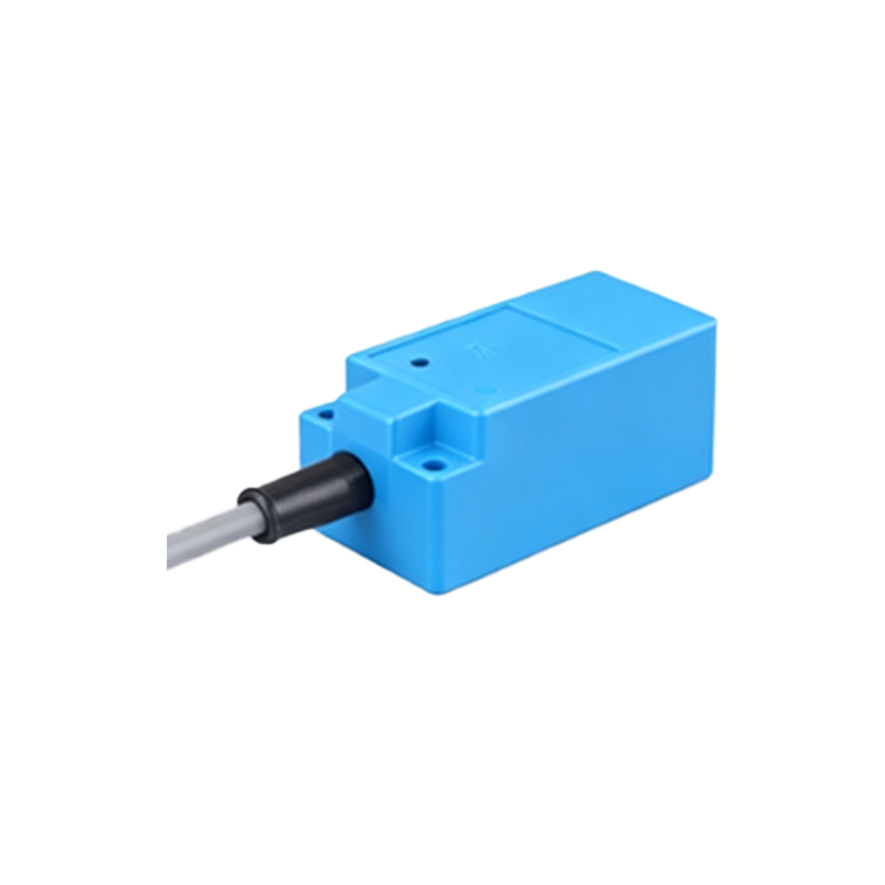
Another critical marking is the electrical rating. This includes the operating voltage range (e.g., 10-30V DC or 20-250V AC), current consumption, and output type (e.g., NPN or PNP for DC sensors, NO/NC contacts). Labels often specify the maximum load current and short-circuit protection details. For instance, "10-30V DC, PNP, NO, 200mA" clearly defines the sensor's electrical parameters. Incorrect interpretation can lead to circuit damage or malfunction.
Environmental ratings are also prominently displayed. Ingress Protection (IP) codes, such as IP67 or IP69K, indicate the sensor's resistance to dust and water. Temperature ratings show the operational range, like "-25°C to +70°C." Materials in contact with the sensed substance may be marked, such as "PBT housing" or "stainless steel face," ensuring compatibility with harsh conditions.
Many sensors include symbols or icons for quick identification. Common symbols represent output types (e.g., a switch icon for digital, a wave for analog), shield status (indicating flush or non-flush mounting capability), and LED indicators for power or output status. Alignment marks for installation might also be present.
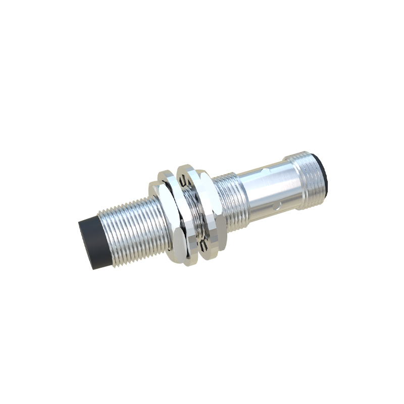
Certification marks from organizations like UL, CE, or ATEX denote compliance with safety and performance standards, especially important in hazardous areas. These marks are often mandatory for specific industries.
Wiring diagrams or terminal designations (e.g., +V, 0V, OUT) are usually provided, either on the label or in accompanying documentation. Correct wiring is essential for functionality and safety.
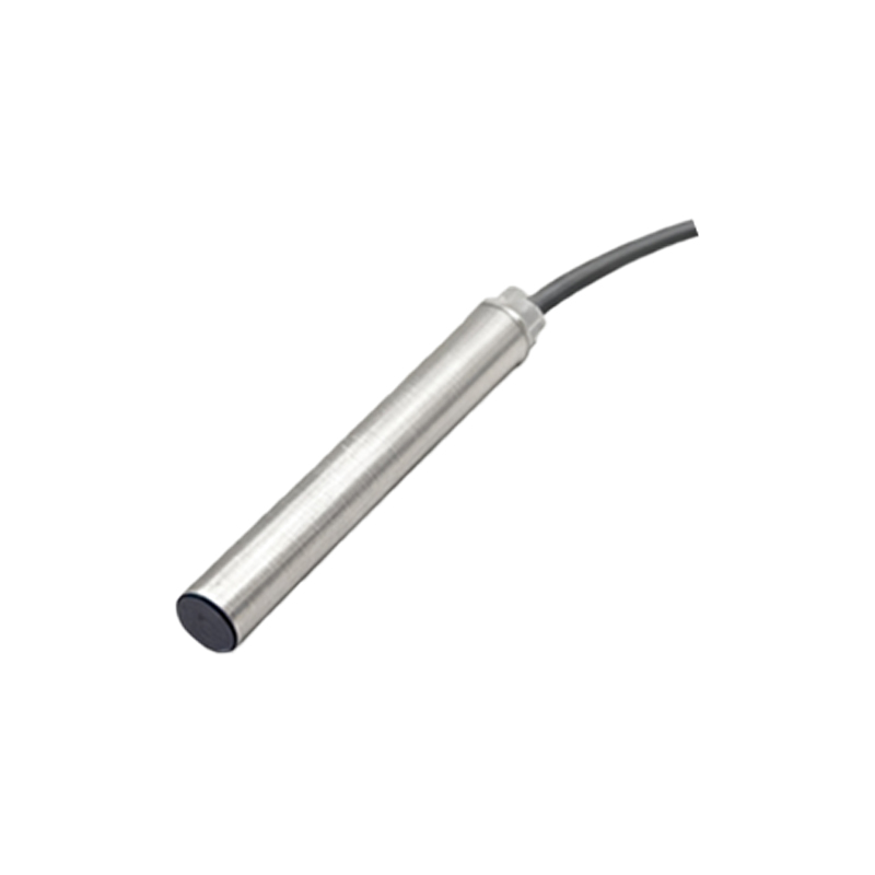
In summary, capacitive proximity sensor markings convey vital technical data. Engineers and technicians should always refer to the manufacturer's datasheet for detailed specifications. Proper interpretation ensures reliable sensor performance, reduces downtime, and enhances system efficiency in applications ranging from packaging machinery to liquid level detection. Regular training on these identifiers is recommended for maintenance personnel.