Designing a reliable circuit for a proximity sensor is a fundamental task in industrial automation, robotics, and safety systems. This guide provides a step-by-step approach to creating a functional circuit diagram, focusing on inductive and capacitive types, which are most common in industrial settings. The goal is to achieve stable detection, noise immunity, and appropriate output signaling.
The core of an inductive proximity sensor circuit involves an oscillator, a detection coil, a demodulator, and an output stage. The oscillator generates a high-frequency electromagnetic field via the coil. When a metallic object enters this field, eddy currents are induced, causing a change in the oscillation amplitude. This change is detected by the demodulator. For the circuit diagram, start by selecting an LC oscillator topology, such as a Colpitts or Hartley oscillator, using a transistor or an integrated oscillator IC. The coil (L) and a capacitor (C) form the resonant tank circuit. Values are chosen based on the desired sensing range and frequency (typically 100 kHz to 1 MHz). A critical design consideration is the quality factor (Q) of the tank circuit; a higher Q increases sensitivity but may reduce stability. Include a small feedback capacitor to sustain oscillations.
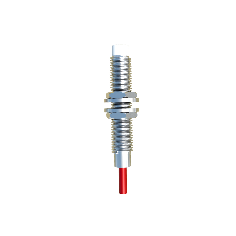
Following the oscillator, a precision rectifier or peak detector circuit acts as the demodulator. It converts the AC oscillation signal into a DC voltage level. This DC voltage is then fed into a comparator stage (e.g., using an LM393). A reference voltage, set by a resistor divider, defines the detection threshold. When the demodulated voltage drops below (for inductive sensors) or rises above (for some capacitive sensors) this threshold, the comparator's output state changes. To prevent false triggering from electrical noise or slow object movement, incorporate hysteresis (Schmitt trigger action) into the comparator circuit. This is achieved by adding a positive feedback resistor between the output and the non-inverting input.
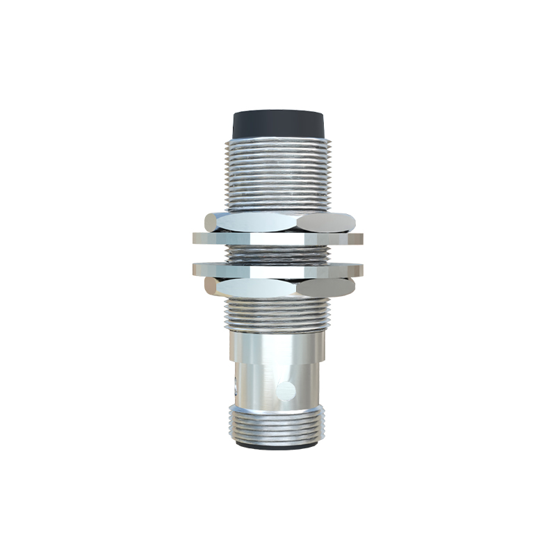
The output stage interfaces the sensor with control systems like PLCs or microcontrollers. Common outputs are NPN (sinking) or PNP (sourcing) transistor configurations. For an NPN output, the collector is connected to the load and positive supply, while the emitter goes to ground. A base resistor limits the current driven by the comparator. Always include a flyback diode across the load (if inductive) to suppress voltage spikes. For a simple two-wire AC sensor, the diagram would show the sensor in series with the load, using a rectifier bridge and a thyristor for switching.
Capacitive proximity sensor circuits share a similar structure but detect changes in capacitance, often from non-metallic materials. The sensing element forms one plate of a capacitor, with the target acting as the other. The circuit often uses a relaxation oscillator or a circuit that measures the charge/discharge time of the sensing capacitor. The frequency or timing change is then converted into a voltage for the comparator. Shielding and guard rings in the diagram are crucial to minimize stray capacitance and environmental interference.
Power supply design is integral to the circuit diagram. Most industrial sensors operate on 10-30V DC. Include a voltage regulator (e.g., 78L05) to provide stable 5V for the ICs. Decoupling capacitors (100nF ceramic and 10µF electrolytic) must be placed near each IC's power pins. For enhanced electromagnetic compatibility (EMC), add ferrite beads and TVS diodes at the power input to suppress surges and conducted noise.
When drafting the final diagram, use standard symbols (IEEE or IEC). Clearly label all components, nodes, and test points. Specify critical parameters: coil inductance, resonant frequency, comparator hysteresis voltage, and output current rating. A well-designed circuit diagram is not just a schematic; it's a blueprint for performance, reliability, and ease of manufacturing. Always prototype and test under realistic conditions, checking for temperature stability, response time, and immunity to adjacent metal or electrical noise.