Proximity sensors are widely used in industrial automation, robotics, and safety systems to detect the presence or absence of objects without physical contact. Proper wiring is crucial for ensuring reliable operation and preventing damage to the sensor or connected equipment. This guide covers common wiring methods, connection steps, and best practices for installing proximity sensors.
Proximity sensors typically fall into two main categories based on their output type: NPN (sinking) and PNP (sourcing). NPN sensors switch the negative side of the load, while PNP sensors switch the positive side. The choice between NPN and PNP depends on the control system's requirements. For example, many PLCs in Europe use PNP inputs, whereas NPN is common in Asia. Always check the sensor datasheet and controller specifications before wiring.
A standard three-wire proximity sensor includes wires for power supply, ground, and output. The brown wire is usually for positive voltage (10-30V DC), the blue wire for ground (0V), and the black wire for the output signal. Some sensors may have additional wires for diagnostic functions or alternate outputs. For two-wire AC/DC sensors, wiring is simpler: one wire connects to power, and the other to the load. However, two-wire sensors may have higher leakage current, which can affect low-power circuits.
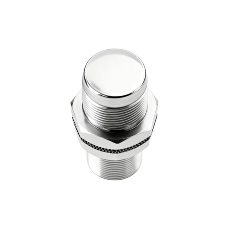
To wire a three-wire DC proximity sensor, first, ensure the power is off. Connect the brown wire to the positive DC supply terminal and the blue wire to the negative terminal. Then, link the black output wire to the input of the controller (e.g., PLC, relay). If using a relay, connect a flyback diode across the coil to suppress voltage spikes. For NPN sensors, the output wire connects to the load, which is then linked to positive voltage. For PNP sensors, the load is connected between the output and ground. Always use shielded cables in electrically noisy environments and ground the shield at one end to prevent interference.
In applications involving multiple sensors, use separate conduits or cable trays to minimize cross-talk. Maintain proper cable lengths—excessive length can cause voltage drop or signal degradation. For long-distance wiring, consider using repeaters or amplifiers. Additionally, ensure the sensor is mounted correctly with adequate clearance from metal objects to avoid false triggers. Adjust the sensing distance as per the manufacturer's guidelines, considering factors like target material and size.
Testing is essential after wiring. Power on the system and verify the sensor's indicator LED activates when an object is within range. Use a multimeter to check output voltage or current. If the sensor fails to respond, recheck connections, polarity, and power supply ratings. Common issues include reversed wiring, insufficient voltage, or incompatible load impedance. Consult troubleshooting charts in the sensor manual for specific error codes.
Regular maintenance, such as cleaning the sensor face and inspecting cables for wear, prolongs sensor life. Store spare sensors in dry, temperature-controlled environments to prevent degradation. By following these wiring practices, users can optimize performance, enhance safety, and reduce downtime in automated systems.