In the realm of industrial automation and electrical engineering, proximity sensors are indispensable components for non-contact detection. Their representation on circuit diagrams and schematics is standardized through specific symbols, which serve as a universal language for engineers, technicians, and designers worldwide. Understanding these symbols is crucial for accurate system design, troubleshooting, and documentation. This guide delves into the common schematic symbols for various types of proximity sensors, explaining their nuances and applications.
The fundamental purpose of a proximity sensor symbol is to convey its operating principle and output type at a glance. Unlike detailed pictorial representations, schematic symbols are abstract, focusing on functional representation. The most common base symbol for a generic proximity sensor resembles a diamond shape with two parallel lines extending from one side, enclosed within a circle. This circle often denotes the device's housing or sensing face. However, significant variations exist based on technology.
Inductive proximity sensors, designed to detect metallic objects, have a distinct symbol. Typically, it incorporates the generic diamond shape but includes a coil symbol (a series of curved lines or a solenoid representation) inside or adjacent to the diamond. This coil symbol explicitly indicates the electromagnetic operating principle. The output line is usually drawn perpendicular to the sensor body. Often, a specific graphical notation, such as a small rectangle or a tag on the output line, signifies the type of solid-state output—PNP (sourcing) or NPN (sinking). International standards like IEC 60617 may depict it with a square representing the electronic amplifier integrated into the sensor.
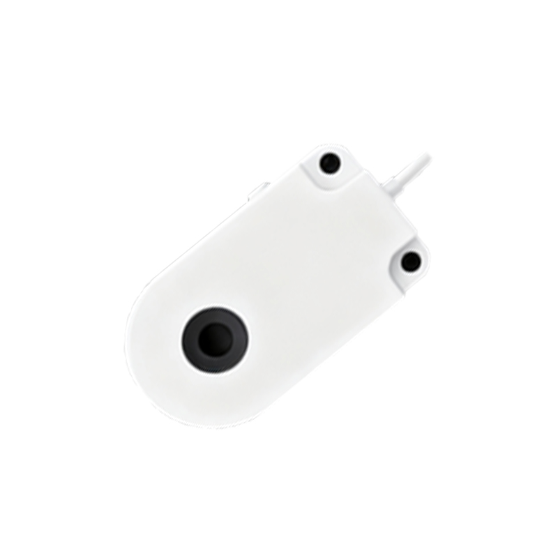
Capacitive proximity sensors, capable of detecting both metallic and non-metallic materials, share a similar outline but are differentiated by their internal marking. The symbol frequently includes two parallel plates or lines within the diamond shape, representing the capacitive plates that form the sensing element. This distinguishes it clearly from the inductive type on a schematic. The output configuration (PNP/NPN, NO/NC) is indicated in the same manner as for inductive sensors.
Ultrasonic proximity sensors use sound waves for detection. Their schematic symbol often incorporates stylized representations of sound waves—concentric arcs emanating from the sensor's face. Sometimes, a small microphone or speaker icon is integrated into the diamond or circle. Photoelectric sensors, another major category, have a highly recognizable symbol: a diamond shape with a diode symbol (a triangle pointing to a line) for the emitter and a phototransistor or photodiode symbol for the receiver. For a thru-beam type, these are two separate symbols (TX and RX) connected by a dashed or dotted line representing the light beam. A retro-reflective type might show both elements in one housing with a specific reflector symbol.
A critical aspect of the symbol is the designation of the switch contact form. Proximity sensors typically provide a digital output acting as a switch. This is shown using standard switch symbology on the output line. A Normally Open (NO) contact is represented by a switch symbol that is open (non-touching) in its unactivated state. A Normally Closed (NC) contact shows a closed (touching) connection in its resting state. The change in this state upon target detection is implied by the sensor's function. The output transistor type (PNP vs. NPN) is paramount for correct wiring to the PLC or controller. While sometimes written as text (e.g., "PNP-NO") near the symbol, it can also be implied by the direction of the output arrow or the specific transistor symbol used on the output line.
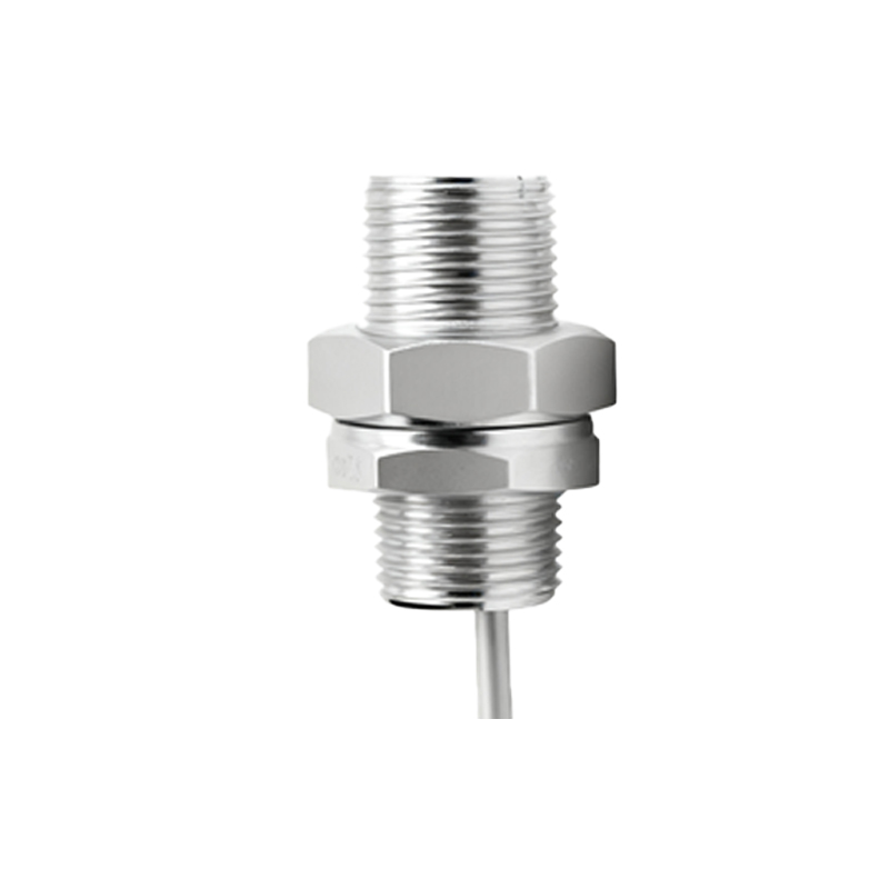
Power supply connections are also part of the complete symbol. Most proximity sensors require a DC supply, denoted as +V (e.g., +24V) and 0V (Common). These connection points are shown as lines or terminals on the symbol, usually on the side opposite the sensing face. A three-wire sensor will clearly show lines for +V, 0V, and the output signal. A two-wire AC or DC sensor symbol will show it integrated into the load line.
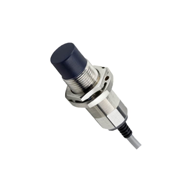
Adherence to international standards ensures clarity. The IEC 60617 standard provides formal symbols, while other organizations like IEEE and ANSI have historically used similar conventions. It is always good practice to include a legend or component list on the schematic detailing the part number, type, and sensing range for each sensor symbol used. When interpreting or creating schematics, paying close attention to these symbolic details prevents wiring errors, ensures compatibility with control systems, and facilitates efficient communication across global engineering teams. Mastery of these symbols is not merely an academic exercise but a foundational skill for effective electrical design and maintenance in automated environments.