In the realm of industrial automation, proximity sensors are indispensable components, enabling non-contact detection of metallic objects with high precision and reliability. While commercial high-power proximity sensors are readily available, designing and building a custom unit can offer tailored performance, cost savings, and a deeper understanding of electromagnetic principles. This guide outlines the process of creating a robust, high-power inductive proximity sensor suitable for demanding environments, adhering to professional engineering standards.
The core of an inductive proximity sensor is an oscillator circuit that generates a high-frequency electromagnetic field. When a metallic object enters this field, eddy currents are induced, causing a change in the oscillator's amplitude or frequency. This alteration is detected, processed, and converted into a switching signal. For high-power applications, the sensor must handle substantial current loads, typically up to 500mA or more, to directly drive relays, solenoids, or contactors without additional amplifiers.
Key components include a ferrite-cored coil, a stable oscillator IC (such as the TCA505 or a custom design using transistors), a robust output stage with a power MOSFET or bipolar transistor, and a durable housing rated for IP67 protection. Begin by winding the coil: use a high-permeability ferrite core (e.g., RM8 or E-core) and enameled copper wire (AWG 22-24). The inductance should range between 1-10 mH, depending on the desired sensing range (typically 5-20 mm for high-power versions). Calculate the number of turns using the core's AL value; for instance, with an AL of 1000 nH/N², approximately 100 turns yield 10 mH. Ensure the coil is tightly wound and secured with epoxy to withstand vibrations.
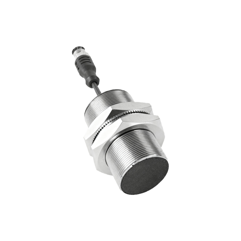
Next, assemble the oscillator circuit. A Colpitts or Hartley configuration using a high-frequency transistor (like BC547 or 2N2222) can generate frequencies between 100 kHz to 1 MHz. Incorporate a feedback network with capacitors and resistors to maintain oscillation stability. The detection circuit often employs a diode demodulator and a comparator (e.g., LM311) to convert amplitude changes into digital signals. For enhanced noise immunity in industrial settings, add filtering capacitors (0.1 µF ceramic and 10 µF electrolytic) near the IC power pins and shield the coil with a grounded metal can, leaving only the sensing face exposed.
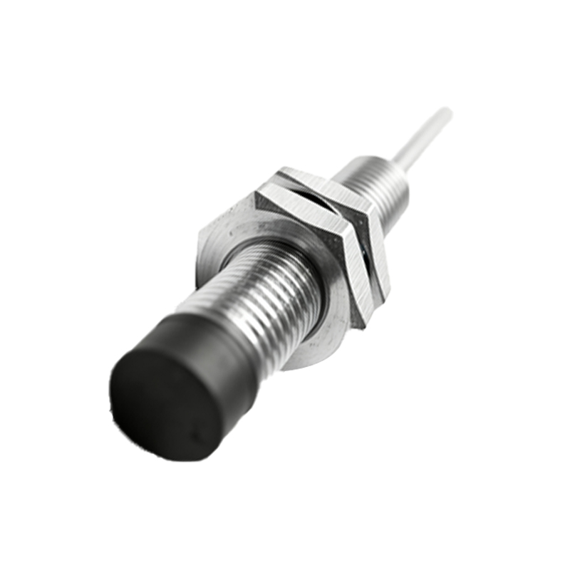
The output stage is critical for high-power operation. Select a logic-level N-channel MOSFET such as the IRF540N, capable of switching currents up to 20A. Drive it via a gate driver IC (e.g., TC4420) to ensure fast switching and prevent thermal issues. Include a flyback diode (1N4007) across the load to suppress voltage spikes from inductive loads. Power the sensor with a regulated 12-24V DC supply, common in industrial systems. Implement overcurrent protection using a resettable fuse or a current-limiting resistor in series with the load.
Calibration involves adjusting the potentiometer in the oscillator or comparator circuit to set the sensing distance. Use a metallic test piece (preferably mild steel, as it offers the best sensitivity) and measure the point where the output toggles. Ensure hysteresis is adequate to prevent chatter; this can be adjusted via feedback resistors around the comparator. Test under varying temperatures and voltage fluctuations to validate stability. For safety, always enclose the circuit in a non-conductive, rugged housing like polycarbonate or aluminum with proper grounding.
Applications for such a DIY high-power proximity sensor include heavy machinery position sensing, conveyor belt object detection, and automated assembly line controls. It offers flexibility in form factor and output configuration (e.g., normally open or closed). However, note that inductive sensors only detect metals; for non-metallic objects, capacitive sensors would be a better choice. Regular maintenance, such as checking for coil damage or output degradation, ensures long-term reliability.
By mastering this DIY project, engineers can customize sensors for specific industrial needs, optimizing parameters like range, response time, and power handling. It also fosters innovation in integrating smart features, such as IO-Link communication or self-diagnostic capabilities, using microcontrollers. Always prioritize safety standards like IEC 60947-5-2 when deploying in real-world systems.