Disassembling a proximity sensor is a common task for maintenance technicians, electricians, and automation engineers. Whether for repair, replacement, or inspection, following a correct and safe procedure is crucial to prevent damage to the sensor or the connected system. This guide provides a detailed, industry-standard approach to disassembling a typical inductive or capacitive proximity switch.
Before starting any disassembly, the foremost step is to ensure complete safety. De-energize the entire circuit or machine where the sensor is installed. Lock out and tag out (LOTO) the power source according to your facility's safety protocols. Verify the absence of voltage using a multimeter at the sensor's wiring terminals. This step is non-negotiable, as working on live equipment poses severe risks of electric shock or causing unexpected machine operation.
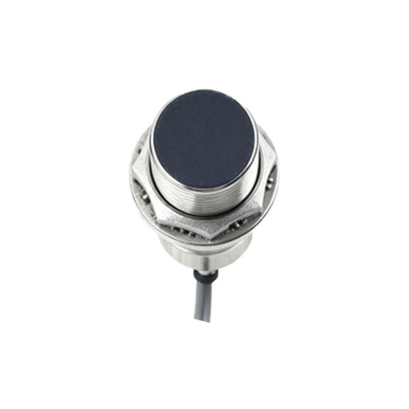
Next, gather the necessary tools. Typically, you will need a set of screwdrivers (flat-head and Phillips, often in smaller sizes), wrenches or socket sets (metric or imperial, depending on the sensor's housing and mounting), and possibly a pair of wire cutters/strippers. For sensors with specialized housings, check if a specific Allen key or Torx driver is required. Having a clean workspace with containers to organize small screws and components is highly recommended to avoid losing parts.
Begin by disconnecting the electrical connections. Most industrial proximity sensors have a quick-disconnect (M12, M8, or other coded connectors) or are directly wired into a junction box. For quick-disconnect types, simply unplug the connector. For hard-wired sensors, carefully note the wiring scheme. It is excellent practice to take a clear photograph of the wiring before disconnecting any wires. Label each wire with its corresponding terminal number (e.g., Brown/+V, Blue/0V, Black/Signal) using tape or tags. Then, loosen the terminal screws and remove the wires. If the wires are fed through a cable gland, you may need to loosen the gland nut later after unmounting the sensor body.
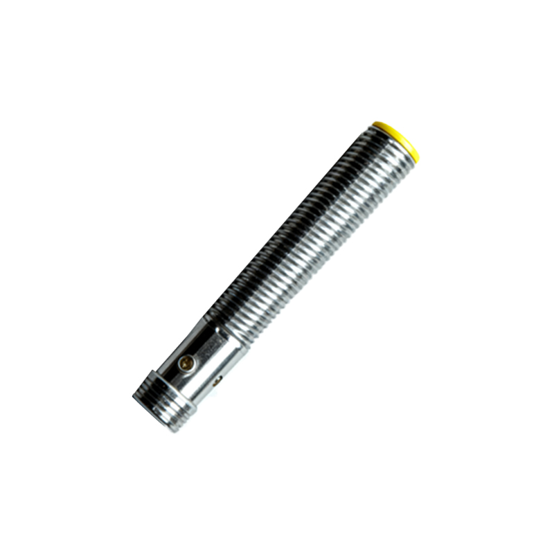
The physical removal of the sensor from its mounting is the next phase. Proximity sensors are commonly mounted using locknuts on threaded barrels or with separate mounting brackets. For a barrel-style sensor, hold the sensor body firmly and use a wrench to loosen the locknut that secures it to the mounting bracket or machine frame. Once the locknut is loose, you can unscrew the entire sensor barrel from its mounting hole. For sensors in block-style housings, locate and remove the mounting screws that fix the housing to its bracket. Be mindful of any sealing gaskets or O-rings that might be present, especially for IP67 or higher-rated sensors, and ensure they are not damaged during removal.
With the sensor detached, you can now proceed to disassemble the sensor unit itself, if required for internal inspection or component replacement. Note that many proximity sensors are sealed units and are not designed for end-user repair; opening them may void the warranty and compromise their ingress protection rating. Only proceed if you are specifically troubleshooting or if the manufacturer's documentation indicates it is serviceable.
If disassembly is appropriate, locate the housing seams. Some sensors have a threaded collar that unscrews, while others may be held together by small screws or a crimped metal ring. Use the appropriate tool to carefully open the housing. Work slowly and evenly to avoid cracking plastic casings or bending metal components. Inside, you will typically find the coil assembly, oscillator circuit, and output switching module (transistor) potted in epoxy or housed in a separate internal casing. At this stage, avoid touching or prying the internal electronics unless you are trained to do so. The goal is often to check for visible damage like cracked potting, burnt components, or corroded connections.
Throughout the process, keep components clean and free from oil, metal chips, or dirt. Contaminants can affect sensor performance upon reassembly. If you are replacing the sensor, this is a good time to clean the mounting hole and area.
For reassembly or installation of a new unit, reverse the steps. Ensure any O-rings or seals are correctly seated. Tighten mounting locknuts or screws to the manufacturer's specified torque to avoid over-tightening, which can crack housings or distort threads. Reconnect the wiring precisely according to your labels or photograph. Finally, after double-checking all connections and mounting, restore power and test the sensor's functionality using a target metal object (for inductive types) to verify correct switching operation.
Remember, always consult the specific sensor's datasheet or manual from the manufacturer (e.g., Siemens, Omron, Schneider Electric, Pepperl+Fuchs) for any model-specific instructions or warnings. Proper disassembly and handling extend the