In the realm of industrial automation and electrical control systems, proximity sensors play a pivotal role in non-contact detection. Among the various types, the magnetic reed proximity sensor stands out for its simplicity, reliability, and cost-effectiveness. Understanding its schematic symbol is fundamental for engineers, technicians, and anyone involved in designing, interpreting, or troubleshooting electrical circuit diagrams. This article delves into the standard representation, functional principles, and contextual application of the magnetic reed proximity sensor symbol in accordance with international electrical drafting standards.
The schematic symbol for a magnetic reed proximity sensor is a composite graphic that conveys both its sensing mechanism and its switching function. At its core, the symbol incorporates the standard representation for a reed switch. This is typically depicted as two parallel, slightly overlapping lines enclosed within a circle or an oval. These two lines represent the ferromagnetic reeds (normally open contacts) that are hermetically sealed within a glass tube. The enclosing circle signifies the protective housing. To indicate the proximity and magnetic actuation aspect, the symbol is almost always accompanied by a distinct graphic element: a small, adjacent rectangle or a bar magnet symbol drawn parallel to the reed switch. This represents the permanent magnet that is either integrated into the sensor's body or is the target actuator. In a standard three-wire DC sensor configuration, the symbol will also include connection points, often labeled as +V (brown wire), 0V (blue wire), and the output signal (black wire). For a PNP (sourcing) output, the switch symbol is connected to the positive supply; for an NPN (sinking) output, it is connected to the negative/0V line.
The operation implied by the symbol is straightforward. When a ferromagnetic target (or the sensor's own integrated magnet approaches an external actuator) enters the predefined sensing range, the magnetic field causes the two reed contacts to attract each other and close. In the schematic, this is represented by the two parallel lines making contact. This closure completes the circuit for the output transistor inside the sensor, allowing current to flow to the load (e.g., a PLC input, relay coil, or indicator lamp). The symbol does not dynamically change in a static drawing; the state (normally open) is implied by the default depiction. Some detailed schematics may include a note specifying "NO" (Normally Open) beside the symbol.
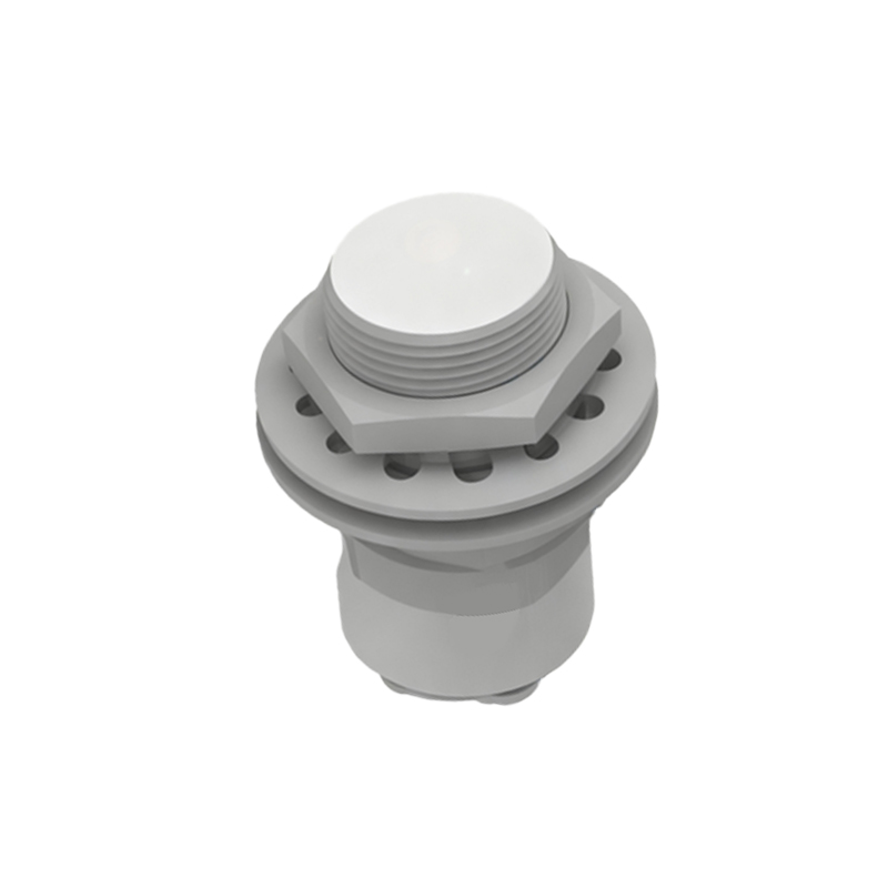
It is crucial to differentiate this symbol from others. A standard mechanical limit switch symbol uses a different contact depiction, often with a hinged lever. An inductive or capacitive proximity sensor symbol replaces the reed/magnet graphic with specific icons: a coil with a front-facing field for inductive, or two parallel plates for capacitive. Recognizing these subtle differences prevents misreading of a circuit's logic. The magnetic reed sensor symbol is predominantly used in applications where the sensing environment is clean and free of strong ambient magnetic fields. Common applications include door and window position detection in security systems, liquid level sensing using float magnets, and speed detection in low-RPM rotational equipment. In a ladder logic diagram, the sensor's output contact symbol is placed as a condition in a rung, controlling the energization of a coil or other output device.
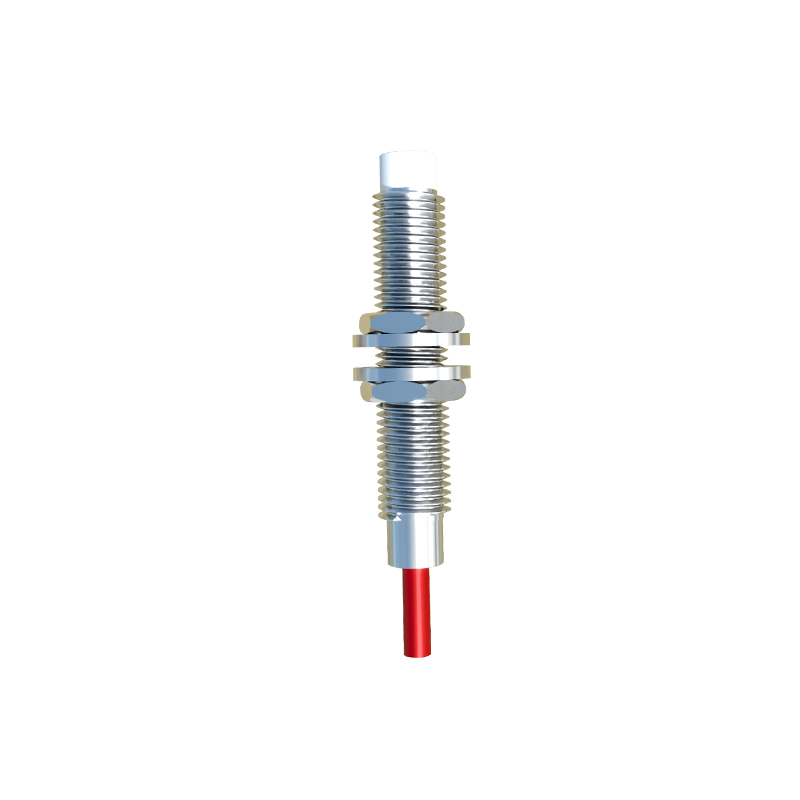
When interpreting a schematic, locating this symbol immediately informs the reader of several key parameters: the sensor is magnetically actuated, it provides a discrete digital ON/OFF signal, and its physical operation relies on the movement of a magnetic field source. Designers must ensure the symbol is correctly annotated with part references (e.g., PRX1, MRS1) and linked to a component list detailing voltage ratings, current capacity, and sensing distance. Mastery of this and other sensor symbols is not merely an academic exercise; it is a practical skill that ensures accurate system design, efficient commissioning, and rapid fault diagnosis in complex electrical control panels. Always cross-reference the schematic symbol with the manufacturer's datasheet for the specific model in use, as variations in internal circuitry (like protection diodes or status LEDs) may be represented with additional schematic elements around the core reed switch symbol.