Proper installation of a lead screw proximity sensor is critical for ensuring accurate position feedback, system reliability, and long-term operational safety in automated machinery. As an electrical engineer with extensive field experience, I will outline a comprehensive, industry-standard procedure for installing these sensors. This guide assumes you have a basic understanding of mechanical and electrical systems and always prioritize safety by disconnecting all power sources before beginning any work.
The first step is preparation and inspection. Verify the sensor model against the system specifications. Check the lead screw assembly for any physical damage, misalignment, or debris that could interfere with the sensor's operation. Ensure the mounting location on the machine frame is clean, flat, and provides a stable, vibration-free base. Gather all necessary tools, including appropriate wrenches, alignment tools, a multimeter, and the sensor's datasheet. Confirm the electrical characteristics—such as voltage, current, output type (PNP/NPN, analog, or digital), and wiring requirements—match your control system.
Mechanical mounting is the foundation of a successful installation. Most lead screw proximity sensors are mounted via a bracket or a threaded housing. Securely fasten the mounting bracket to the designated spot on the machine frame, ensuring it is rigid and perpendicular to the lead screw's axis of travel. The sensor itself must be positioned so its sensing face is parallel to and at a precise distance from the target—typically a flag, notch, or specific section of the lead screw nut or carriage. This gap, known as the sensing distance, is specified in the datasheet (e.g., 2mm, 5mm). Use a feeler gauge to set this distance accurately. Avoid mounting the sensor where it could be exposed to excessive heat, coolant splash, or metal chips. Once positioned, tighten the mounting hardware to the manufacturer's recommended torque, but avoid over-tightening, which can distort the housing and affect performance.
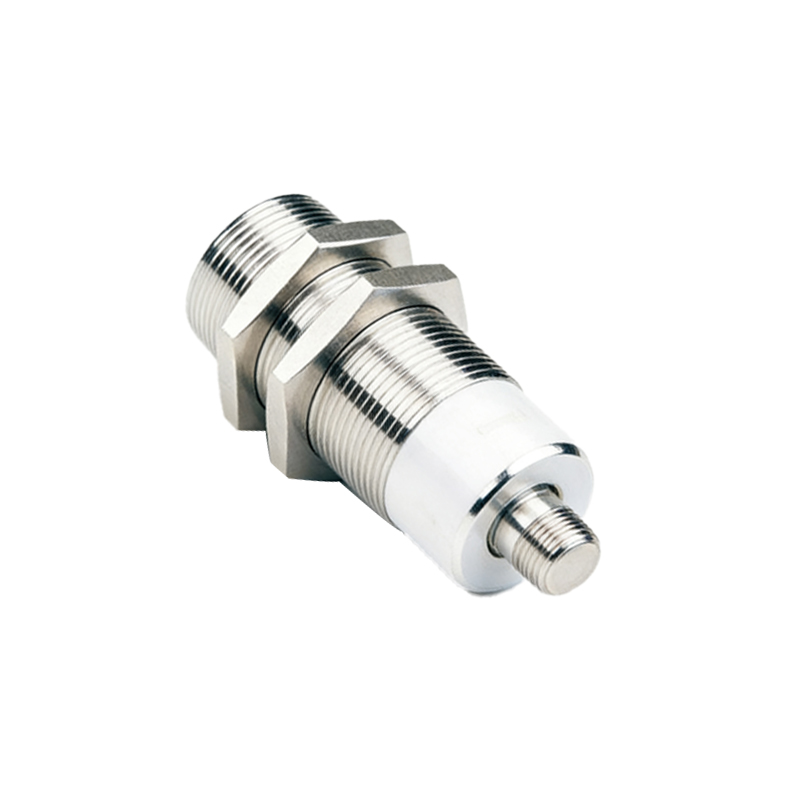
Electrical connection follows mechanical securement. Run the sensor cable through conduit or cable carriers if available to protect it from abrasion and EMI. Strip the cable ends as needed. Connect the wires according to the wiring diagram: typically, a 3-wire DC sensor will have brown (power+), blue (power-), and black (output) wires. Connect the power leads to a stable DC supply within the sensor's rated range. The output wire connects to the designated input on your PLC, drive, or controller. Double-check all connections for correctness and secureness. Use ferrules or proper terminal blocks to ensure reliable contact. It is good practice to include a small fuse in the power line for protection.
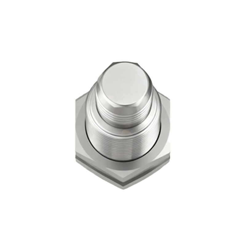
After wiring, perform alignment and functional testing before powering the main system. Temporarily apply power to the sensor circuit only. Use a multimeter to check the voltage at the sensor's power terminals. Manually move the lead screw carriage so the target passes through the sensor's detection zone. Observe the sensor's indicator LED (if present) and measure the output signal with your multimeter. The output should switch states (e.g., from 0V to 24V for a PNP sensor) when the target is detected. Verify the sensing is consistent and repeatable across the entire required travel range. If the sensor has adjustable sensitivity, make fine-tuning adjustments now to achieve a clean, chatter-free signal.
Finally, conduct a full system integration test. With all safety checks complete, restore power to the entire machine system. Jog or slowly command the lead screw to move through its programmed cycle. Monitor the sensor's feedback on the controller's diagnostic interface. Ensure the position detection triggers at the exact intended points without false triggers or missed signals. Document the installation, noting the sensor location, gap setting, and any adjustments made. Regular maintenance should include periodic checks of the mounting integrity, cleanliness of the sensing face, and signal stability.
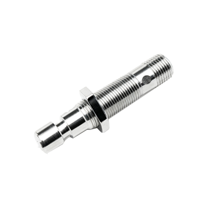
Common pitfalls to avoid include incorrect gap setting, which is the leading cause of failure; misalignment causing inconsistent detection; electrical noise from nearby motors or drives interfering with the signal (use shielded cables and proper grounding); and selecting a sensor with an insufficient sensing range or environmental rating (IP rating) for the application. Always consult the manufacturer's installation manual for model-specific details.