Proximity sensors are essential components in modern sliding door systems, providing reliable detection for automated operation. Proper wiring is critical to ensure safety, functionality, and longevity. This guide outlines the step-by-step process for wiring a proximity sensor in sliding door applications, adhering to industry standards and best practices.
First, identify the sensor type. Inductive proximity sensors are commonly used for metal door frames, while capacitive sensors suit non-metallic materials. Check the sensor specifications, including voltage rating (typically 12-24V DC or 110-240V AC), output type (PNP or NMP), and sensing range. Ensure the sensor is compatible with the door controller.
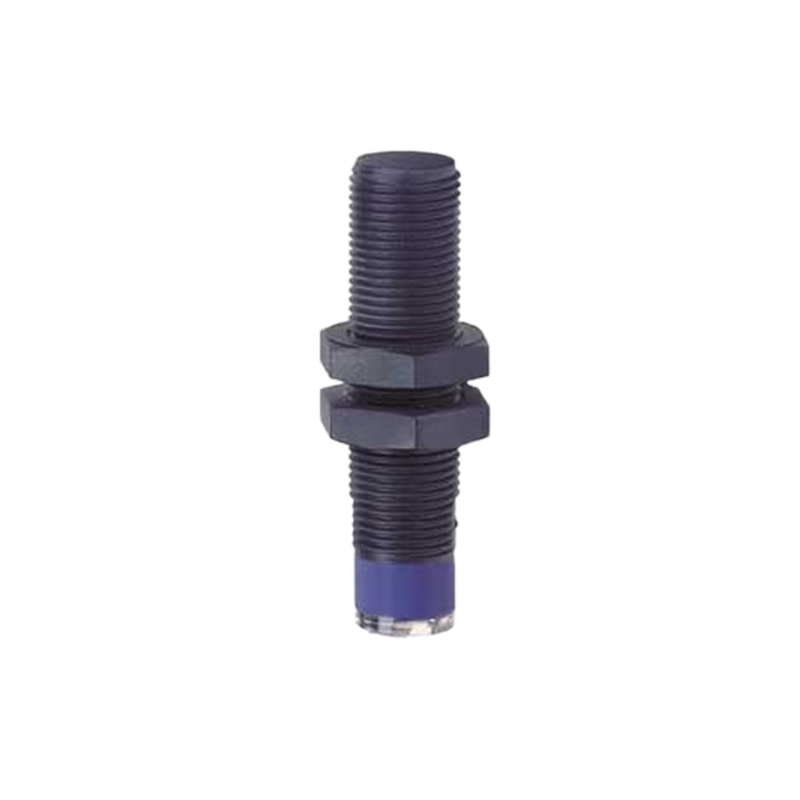
Begin by disconnecting all power sources to prevent electrical hazards. Mount the sensor in the designated location, usually near the door edge or track, aligning it within the recommended sensing distance. Secure the sensor firmly to avoid vibration-induced misalignment.

Next, prepare the wiring connections. Most proximity sensors have three wires: brown (power+), blue (power-), and black (output signal). For DC sensors, connect the brown wire to the positive terminal and the blue wire to the negative terminal of the power supply. For AC sensors, brown typically connects to live (hot) and blue to neutral. The black output wire links to the control input of the door actuator or PLC. If using a shielded cable, ground the shield at the controller end to minimize interference.
Incorporate protective measures. Install a fuse or circuit breaker on the power line, rated slightly above the sensor’s current draw. Use conduit or cable trays in industrial environments to protect wires from physical damage. For long cable runs, consider voltage drop and use thicker gauges if necessary.
Testing is crucial. After wiring, restore power and verify the sensor’s indicator LED activates when metal (or target material) enters the sensing range. Check the output signal with a multimeter to confirm voltage switching. Adjust the sensor position if detection is inconsistent.
Finally, integrate with the door system. Connect the sensor output to the controller’s safety circuit, ensuring it triggers door reversal or stop functions upon obstruction detection. Calibrate sensitivity settings according to the manufacturer’s guidelines to avoid false triggers.
Regular maintenance includes inspecting wire insulation for wear, cleaning the sensor face, and verifying alignment annually. Proper wiring not only enhances safety but also reduces downtime in high-traffic areas like hospitals, warehouses, and commercial buildings.
Always refer to the sensor and door system manuals for model-specific instructions. When in doubt, consult a certified electrician to comply with local electrical codes.