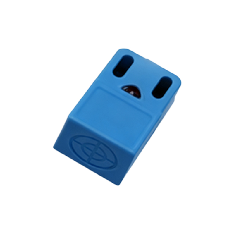
Metal proximity sensors are critical components in industrial automation, offering non-contact detection of metallic objects with high reliability. The manufacturing process of these sensors involves sophisticated engineering techniques to ensure precision, durability, and consistent performance. This article delves into the key stages of production, from material selection to final testing, highlighting industry best practices.
The foundation of a high-quality metal proximity sensor lies in its core materials. Typically, the sensing element is crafted from ferrite or laminated steel, chosen for their magnetic permeability and stability. The coil, often made of copper wire with precise winding specifications, generates an electromagnetic field that detects metallic targets. The housing, usually constructed from stainless steel, brass, or engineered plastics like PBT, provides mechanical strength and environmental protection. Material purity and consistency are rigorously controlled to prevent performance deviations, with suppliers adhering to ISO 9001 standards for quality assurance.
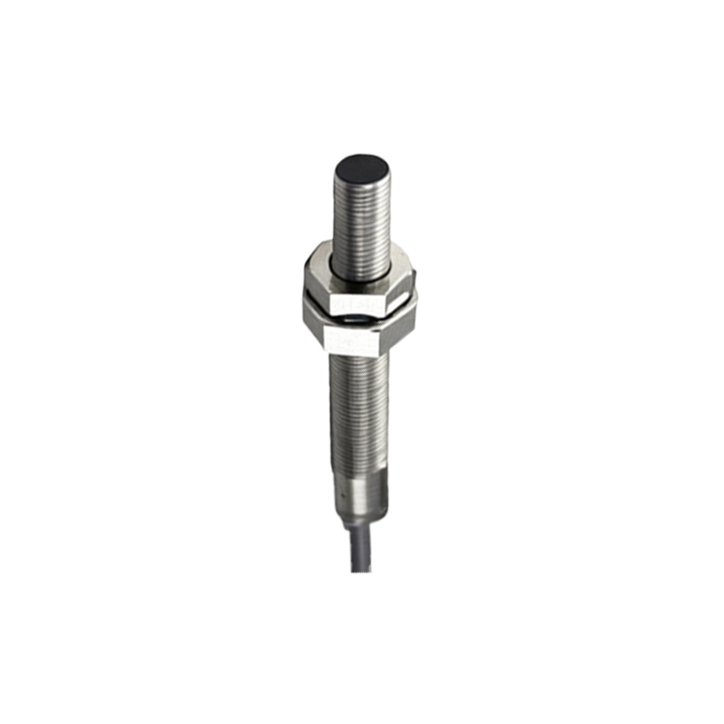
In the assembly phase, automated machinery ensures accuracy and efficiency. The coil winding process utilizes CNC-controlled machines to achieve uniform turns, which directly impacts the sensor's sensitivity and range. This coil is then integrated with the ferrite core using epoxy resins that offer excellent thermal and chemical resistance. The housing components are machined or molded to tight tolerances, often within ±0.1 mm, to guarantee proper sealing against dust, moisture, and oils. Advanced techniques like laser welding or ultrasonic bonding are employed for hermetic sealing, crucial for sensors deployed in harsh environments such as automotive or heavy machinery applications.
Electronic circuitry is another vital aspect. The oscillator circuit, which drives the coil, is designed with surface-mount technology (SMT) on printed circuit boards (PCBs). Components like transistors, resistors, and integrated circuits are selected for low power consumption and high-temperature resilience. Calibration follows assembly, where each sensor undergoes frequency tuning to match specified detection distances—commonly ranging from 2 mm to 40 mm, depending on the model. Automated test benches simulate real-world conditions, checking parameters such as switching frequency, hysteresis, and temperature drift from -25°C to 70°C.
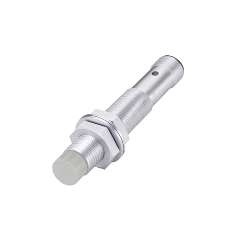
Quality control is embedded throughout the manufacturing workflow. In-process inspections include X-ray analysis to verify internal solder joints and coil integrity. Final products are subjected to endurance tests, such as 10 million operation cycles, to validate longevity. Compliance with international standards like IEC 60947-5-2 ensures safety and interoperability. Additionally, many manufacturers implement traceability systems, marking each sensor with a unique QR code for tracking from production to deployment.
Innovations in manufacturing continue to evolve. For instance, additive manufacturing (3D printing) allows for rapid prototyping of custom housings, while AI-driven optical inspection enhances defect detection. The trend toward miniaturization demands finer precision in micro-sensor production, often requiring cleanroom environments to prevent contamination. As industries embrace Industry 4.0, smart sensors with embedded diagnostics are becoming standard, incorporating communication protocols like IO-Link for real-time monitoring.
In summary, the production of metal proximity sensors blends traditional craftsmanship with cutting-edge technology. By adhering to stringent processes and continuous improvement, manufacturers deliver devices that enhance automation efficiency, reduce downtime, and support sustainable industrial operations. For engineers and procurement specialists, understanding these manufacturing nuances aids in selecting the right sensor for specific applications, from conveyor systems to robotic arms.