In industrial automation and advanced electronic systems, the 20s proximity sensor represents a critical component for non-contact object detection, position sensing, and automated process control. A recurring and disruptive failure mode reported across various sectors is the "black screen anomaly," where the sensor's indicator or connected interface display fails entirely, ceasing all visual feedback while the sensor may or may not continue partial operation. This phenomenon poses significant risks to operational continuity, safety protocols, and data integrity. This article delves into the root causes, diagnostic methodologies, and systematic resolution strategies for this specific failure.
The black screen symptom is distinct from simple target detection failure. It indicates a breakdown in the sensor's internal processing, power delivery, or communication pathway to its human-machine interface (HMI). The primary culprits can be categorized into three domains: power integrity, signal processing chain failure, and firmware/software corruption.
1. Power Integrity and Supply Issues:
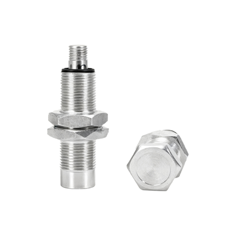
The most common origin of a complete black screen is an unstable or insufficient power supply. Proximity sensors, especially industrial-grade models like the 20s series, have strict voltage tolerances (e.g., 10-30V DC). Voltage spikes, brownouts, or excessive ripple from a degraded power supply unit can trigger internal protection circuits, forcing a shutdown of non-essential functions, including the display driver. Furthermore, poor wiring connections, corroded terminals, or damaged cables can create high-resistance points, leading to a significant voltage drop at the sensor itself. A multimeter check at the sensor's power input terminals under load is the first diagnostic step. The voltage must remain within the specified range during operation.
2. Internal Signal Processing and Hardware Failure:
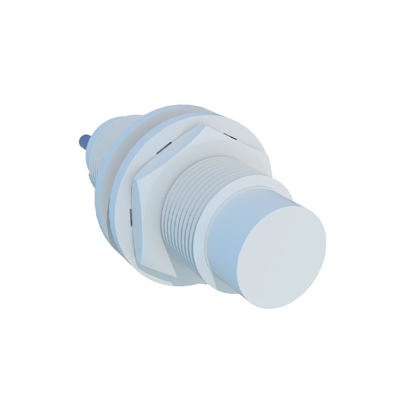
If power is confirmed stable, the fault may lie within the sensor's internal hardware. The core oscillator circuit, which generates the electromagnetic field for detection, is fundamental. A failure here can cause the main microcontroller to enter a fault state, halting all outputs, including display signals. Similarly, a damaged display driver IC or a fractured connection on the internal PCB (e.g., from excessive vibration or thermal stress) can directly cause the screen to go black. In some cases, the sensing element itself might be intact, but the processing unit that formats data for the display has malfunctioned. Environmental factors are key accelerants: prolonged exposure to ambient temperatures beyond the sensor's rating, conductive dust contamination, or moisture ingress can lead to short circuits or component degradation.
3. Firmware Glitches and Communication Errors:
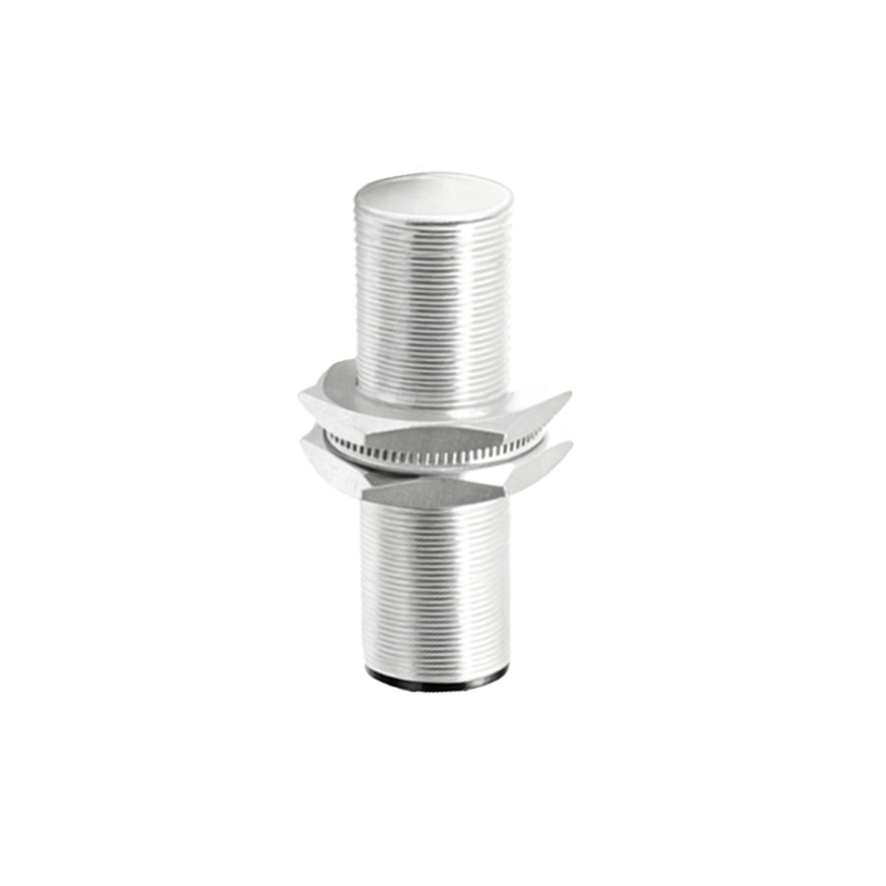
Modern proximity sensors are intelligent devices running embedded firmware. A corrupted firmware memory block or a software lock-up due to an unhandled exception can manifest as a black screen. This can occur after a power interruption during a firmware update or from electromagnetic interference (EMI) corrupting memory registers. For sensors communicating via IO-Link, Profinet, or other industrial networks, a severe communication protocol error or address conflict might cause the sensor to reset or enter a safe mode, disabling the local display. Cycling power might temporarily resolve a soft lock-up, but the root cause often requires a firmware reflash or parameter reset.
Systematic Troubleshooting Protocol:
A methodical approach is essential to isolate the fault.
Step 1: Visual and Environmental Inspection: Check for physical damage, loose connectors, and environmental conditions (temperature, humidity, particulate levels). Verify the target is within the sensor's specified sensing range and material compatibility.
Step 2: Power Supply Verification: Using a calibrated digital multimeter, measure the DC voltage at the sensor's terminals. Check for both the correct nominal voltage and the absence of excessive AC ripple (should be<5% of DC voltage).
Step 3: Output Signal Check: Even with a black screen, the sensor's switching output (PNP/NPN) may still be active. Use a multimeter or oscilloscope to monitor the output signal when a valid target is presented. If the output functions correctly, the issue is isolated to the display subsystem. If there is no output, the core sensor functionality is compromised.
Step 4: Substitution and Isolation: The most effective test is to replace the suspect sensor with a known-good unit of the same model under identical conditions. If the new unit operates normally, the original sensor is faulty. Also, isolate the sensor from the network (if connected) to rule out bus communication issues.
Step 5: Configuration Check: If applicable, use configuration software to attempt to connect to the sensor. A successful connection but lack of display points to a dedicated HMI failure. An inability to connect suggests a deeper hardware or firmware fault.
Preventive Measures and Best Practices:
Preventing the black screen anomaly is more efficient than reactive repair. Implement these practices:
Ensure stable, clean power