In industrial automation and electrical control systems, proximity sensors are indispensable components for non-contact detection of metallic or, in some cases, non-metallic objects. As an electrical engineer, understanding how to properly measure the voltage at a proximity sensor is a fundamental diagnostic and commissioning skill. This process is critical for verifying correct power supply, diagnosing faults, ensuring signal integrity, and integrating the sensor seamlessly into a larger control system, such as a PLC (Programmable Logic Controller) network.
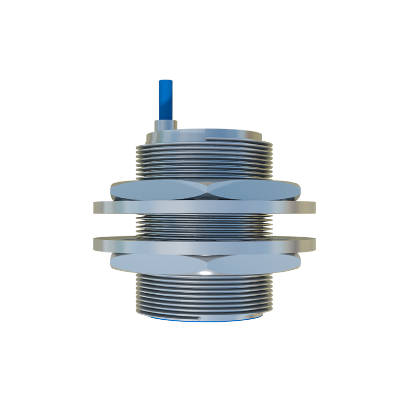
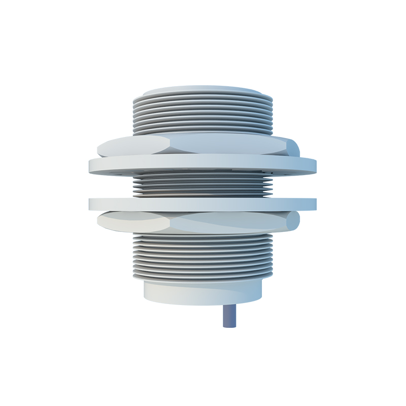
Before any measurement, the paramount rule is safety. Always ensure the control circuit is de-energized and locked out/tagged out (LOTO) before handling wiring. Once safe, identify the sensor type and its wiring scheme. The two most common DC output types are 3-wire and 4-wire sensors, which can be PNP (sourcing) or NNP (sinking). A 2-wire AC/DC sensor is also common. Consult the sensor's datasheet for its specific electrical characteristics: operating voltage range (commonly 10-30V DC), output type, and current rating.
The core tool for this task is a digital multimeter (DMM). Ensure it is rated for the voltage you are measuring and set to the correct function (DC Voltage for most modern sensors) and a range exceeding the supply voltage (e.g., 200V DC scale for a 24V DC system).
Measuring Supply Voltage (Power Verification):
This is the first check. For a 3-wire DC sensor:
1. Identify the wires: Typically Brown (+V), Blue (0V/Common), and Black (Output).
2. Re-energize the circuit with all connections secure.
3. Set your DMM to DC Volts.
4. Place the black (common) meter probe on the Blue wire (or a verified system common/ground point).
5. Place the red (positive) meter probe on the Brown wire.
6. The reading should be within the sensor's specified range (e.g., 24V DC ±10%). A reading of zero indicates a blown fuse, tripped breaker, or wiring fault upstream. A low reading suggests potential overload or supply issues.
Measuring Output Voltage (Signal Verification):
This confirms the sensor's switching function. The procedure differs for PNP vs. NNP sensors.
For a PNP (Sourcing) Sensor:
1. Keep the DMM's black probe on the Blue wire (common).
2. Place the red probe on the Black (output) wire.
3. When the sensor is not detecting a target (its normal state), the output should be near 0V DC (e.g.,<1V), indicating it is not sourcing voltage.
4. When a valid target is presented within the sensing range, the output should switch to a voltage close to the supply voltage (e.g., ~24V). This "high" signal is read by the PLC input card.
For an NNP (Sinking) Sensor:
1. This time, place the DMM's red probe on the Brown wire (+V supply).
2. Place the DMM's black probe on the Black (output) wire.
3. When not detecting, the output should be near supply voltage (the output is "open").
4. When detecting, the output should switch to near 0V DC, as it now sinks current to common.
Measuring Voltage Drop (for 2-Wire Sensors):
Two-wire sensors are wired in series with the load. To check function:
1. Measure the voltage across the sensor's two terminals.
2. When inactive (off), almost the full supply voltage will appear across the sensor.
3. When active (on) and switching the load, a small voltage drop (typically 1.5-3V DC) will appear across it, and the load should energize.
Troubleshooting Based on Voltage Readings:
No Supply Voltage: Check fuses, circuit breakers, power supply unit, and continuity of wiring.
Supply OK, No Output Change: Ensure the target is correct material and size, and within the sensing distance. Check for sensor damage or misalignment.
Output Voltage Sagging: When activated, the output voltage drops significantly below supply (e.g., to 12V). This indicates potential overload—the sensor's output current may be exceeding its rating, often due to a short circuit or a PLC input module with too low an impedance. Check the load.
Incorrect Output State: A PNP sensor showing ~24V constantly may be stuck on or wired incorrectly. Cons