Proximity sensor switches are fundamental components in modern industrial automation, enabling non-contact detection of metallic or non-metallic objects. Their correct installation and wiring are paramount for ensuring system reliability, safety, and optimal performance. This guide details standard wiring methods for common 3-wire DC and AC proximity sensors, along with critical considerations for practical application.
The vast majority of industrial proximity sensors utilize a 3-wire configuration. For DC sensors, the standard wire color coding is typically brown for positive supply (+V), blue for negative supply (0V or common), and black for the output signal. It is crucial to always verify the manufacturer's datasheet, as colors can vary. DC sensors come in two output types: NPN (sinking) and PNP (sourcing). Understanding this distinction is the cornerstone of correct wiring.
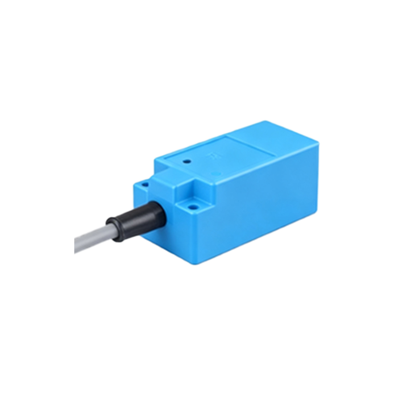
An NPN sensor switches the negative (0V) line. In its normal state, the output (black wire) is internally disconnected. When an object is detected, the sensor internally connects the black output wire to the blue wire (0V), effectively "sinking" current to ground. To complete the circuit, the load (e.g., a PLC input, relay coil) must be connected between the brown wire (+V) and the black output wire. When activated, current flows from +V, through the load, into the black wire, and is sunk to 0V by the sensor.
Conversely, a PNP sensor switches the positive (+V) line. In its normal state, the output is disconnected. Upon detection, it internally connects the black output wire to the brown wire (+V), "sourcing" current from the supply. Here, the load must be connected between the black output wire and the blue wire (0V). When activated, current is sourced from +V through the sensor's internal switch, out the black wire, through the load, and back to 0V.
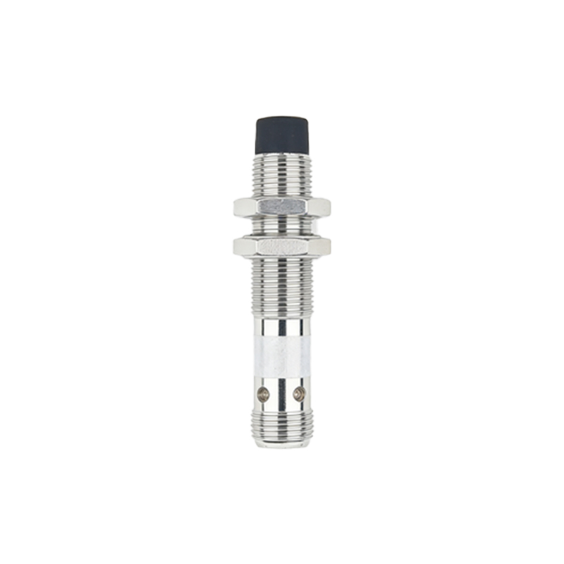
Mixing NPN and PPN wiring with incompatible PLC inputs is a common error. Many PLCs are designed to accept either sinking (NPN-compatible) or sourcing (PNP-compatible) inputs. Attempting to connect an NPN sensor to a sinking-input PLC using the PNP wiring method will result in no signal.
For 3-wire AC sensors, the typical wiring involves brown for live (L+ or Line), blue for neutral (N), and black for the output. The output is usually a solid-state switch. The load is connected in series with the black output wire and the AC supply. For example, one side of the load connects to neutral (blue), and the other side connects to the black wire. The black wire is then connected to the live (brown) supply. Alternatively, the load can be placed between live and the black wire, with the black wire connected to neutral. Always follow the specific diagram provided.
Shielded cable is highly recommended for long cable runs or in electrically noisy environments. The cable shield (drain wire) should be connected to a solid earth ground at the control panel end only, typically at the PLC's grounding terminal. Do not connect the shield at both ends, as this can create ground loops. Ensure the sensor's metal housing is also properly grounded if applicable.
Key practical considerations include: 1) Load Compatibility: Verify the sensor's maximum output current rating is not exceeded by the load. For heavy loads like contactor coils, always use an intermediate relay. 2) Inductive Load Protection: When driving DC relays or solenoids, connect a flyback diode (reverse-biased) across the coil to suppress voltage spikes. For AC loads, an RC snubber network is often used. 3) Wiring Integrity: Use ferrules on stranded wires for secure screw terminal connections. Maintain proper separation from high-voltage power cables to avoid inductive coupling and false triggers. 4) Sensor Power: Ensure a stable, ripple-free power supply within the sensor's specified voltage range. Voltage spikes or drops can cause erratic behavior or damage. 5) Testing: Before full system integration, test the sensor's operation with the actual load using a multimeter to verify output voltage switching.
In complex multi-sensor systems, careful planning of the common (0V) and positive rails is essential. For panels with numerous PNP sensors, a robust common (0V) bus bar is necessary. For systems with many NPN sensors, ensure the positive (+V) distribution can handle the combined leakage currents when sensors are in the off-state.
By meticulously following the correct wiring methodology for the specific sensor type (NPN/PNP/AC), adhering to manufacturer specifications, and implementing noise suppression and protection techniques, engineers can ensure proximity sensors deliver precise, reliable, and long-lasting service in any automated control system.