In the realm of industrial automation and machine safety, proximity sensors with integrated indicator lights are ubiquitous components. Their schematic diagrams, while seemingly straightforward, encapsulate the elegant integration of sensing technology and visual feedback. This article delves into the typical schematic representation of such a device, explaining the function of each component and the signal flow from detection to indication.
A standard inductive proximity sensor with an LED light comprises three primary sections: the oscillator and sensing coil, the signal processing and switching circuit, and the indicator circuit. The core of the sensor is the LC oscillator circuit formed by the sensing coil (L) and a capacitor (C). In the schematic, this coil is depicted adjacent to the sensor's active face. When powered, this oscillator generates a high-frequency electromagnetic field. When a metallic target enters this field, eddy currents are induced in the target, causing a change in the oscillator's amplitude. This amplitude change is the fundamental detection signal.
This signal is fed into a threshold detection or trigger circuit, often involving a comparator or a specialized IC. In the schematic, this is represented by a triangular symbol (comparator) or a block labeled as a processing unit. When the amplitude drop exceeds a predefined threshold, the comparator's output state changes. This output directly controls the solid-state switching element, which is almost universally a transistor or a MOSFET in modern DC sensors. In a typical 3-wire DC sensor schematic (Brown wire: +V, Blue wire: 0V, Black wire: Output), this switching transistor is connected in series with the load between the black output wire and either the positive or negative rail, defining a PNP (sourcing) or NPN (sinking) configuration.
The indicator LED circuit is cleverly integrated in parallel with the main switching path. A current-limiting resistor is always present in series with the LED to protect it. The LED's illumination is typically tied to the sensor's state. In a common design, the LED is connected such that it lights when the output transistor is in the "on" state, providing a direct visual confirmation that the sensor has detected an object and its output is active. Some advanced schematics may show the LED driven by a separate pin from the processing IC, allowing for different blinking patterns to indicate power, short-circuit, or other status conditions.
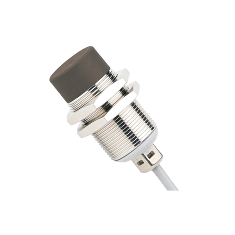
Examining a detailed schematic, one would see the power supply pins (Vcc and GND) decoupled with a small capacitor to filter high-frequency noise. The sensing coil is shown connected to the oscillator circuit, which is part of the IC or built from discrete components. The output from the oscillator stage goes to the detection circuit. The output of the detection circuit then branches: one path goes to the base (or gate) of the output transistor, and another path goes to drive the LED circuit. The collector (or drain) of the output transistor is connected to the output terminal (black wire), while the emitter (or source) is tied to either Vcc (for PNP) or GND (for NPN). The LED and its series resistor are connected between the controlled output node and the appropriate supply rail, ensuring it mirrors the output state.
Understanding this schematic is crucial for troubleshooting. If the sensor fails to detect but the LED lights, the issue may lie in the load circuit or wiring, not the sensing core. Conversely, if the LED fails to illuminate upon detection, the problem could be isolated to the LED or its current-limiting resistor, while the main switching function might still be operational. The schematic serves as the roadmap for diagnosing such faults efficiently.
In conclusion, the schematic diagram of a proximity sensor with an indicator light reveals a harmonious system where sensing, logic, switching, and indication coalesce. It demystifies the internal operation, showing how the invisible electromagnetic field disturbance is converted into a robust electrical switch signal and a clear visual cue. For engineers and technicians, proficiency in reading this schematic is fundamental to effective system design, integration, and maintenance in automated environments.