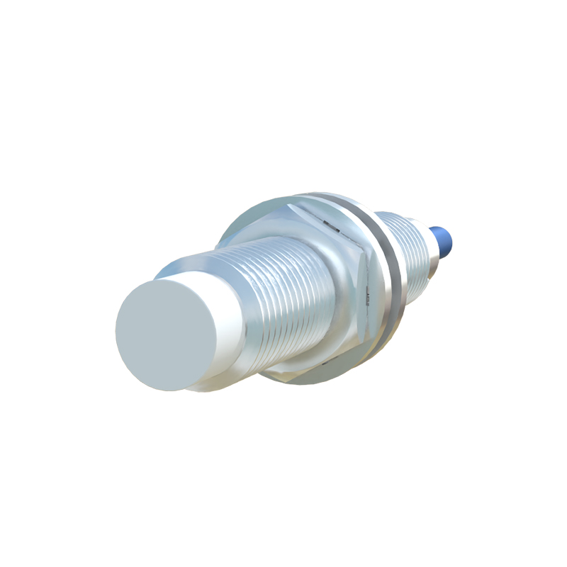
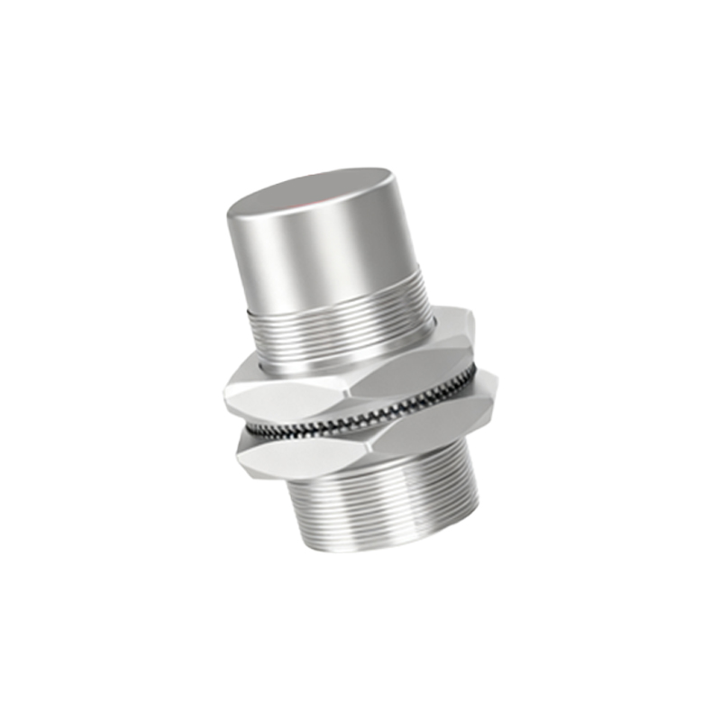
In industrial automation and control systems, proximity sensors play a pivotal role in non-contact object detection. Among the various output configurations, sensors utilizing a KP-type thyristor (also known as a Silicon Controlled Rectifier or SCR) as the switching element are highly valued for their robustness and ability to handle significant AC loads directly. This article provides a detailed technical specification and operational guide for the key parameters associated with the KP thyristor commonly integrated into AC 2-wire proximity sensors.
The primary function of the KP thyristor in this context is to act as a solid-state switch for alternating current (AC) circuits. Unlike transistor outputs, a thyristor, once triggered into conduction (latched on), will remain conducting as long as the anode current remains above its holding current, regardless of the state of the trigger signal. It only turns off when the AC current naturally crosses zero. This characteristic makes it ideal for switching AC loads such as solenoids, contactor coils, and small AC motors.
Critical Electrical Parameters:
1. Blocking Voltage (V_DRM / V_RRM): This is the maximum repetitive peak voltage the thyristor can block in both forward and reverse directions without turning on unintentionally. For standard industrial sensors, common ratings are 140V, 240V, or 400V, corresponding to typical AC line voltages of 100-120VAC and 200-240VAC. Selecting a sensor with a blocking voltage significantly higher than the peak supply voltage is crucial for reliability and surge immunity.
2. On-State Current (I_T(AV) & I_T(RMS)): This defines the maximum continuous average or RMS load current the thyristor can safely conduct. A common rating for many industrial proximity sensors is 200mA. It is imperative that the connected load's steady-state current does not exceed this value. The I_T(RMS) rating is particularly important for AC applications as it reflects the heating effect of the current.
3. Surge Current (I_TSM): This parameter indicates the maximum non-repetitive peak current the thyristor can withstand for a short duration, typically one half-cycle of the AC line (e.g., 10ms at 50Hz). This rating is vital for handling the high inrush currents associated with inductive loads like coils and motors. A typical I_TSM rating might be 3A for a 200mA device.
4. Gate Trigger Current (I_GT) and Voltage (V_GT): These parameters specify the minimum current and voltage required at the gate terminal to reliably switch the thyristor into conduction. In a proximity sensor, the internal oscillator and detection circuit provide this trigger signal. The values are typically low (e.g., 5-50mA) and are internally matched by the sensor's design. Understanding these is more critical for circuit designers than for end-users.
5. Holding Current (I_H): This is the minimum anode current required to keep the thyristor in the conducting state after it has been triggered. If the load current falls below this value (which can happen with very low-power loads or due to leakage), the thyristor may turn off prematurely and erratically. This is a key reason why a minimum load requirement (e.g., 5mA or 10mA) is often specified for AC 2-wire sensors.
6. On-State Voltage Drop (V_T): When conducting, the thyristor exhibits a forward voltage drop, usually between 1V to 1.5V. This drop, combined with other internal circuitry, results in a residual voltage or "leakage current" (typically 1.5-3mA) flowing through the load even when the sensor is in the OFF state. This must be considered when connecting highly sensitive control inputs.
Application Considerations and Protection:
Load Compatibility: Ensure the load (inductive, resistive, or capacitive) characteristics fall within the thyristor's ratings. Exceeding the I_T(AV) rating will lead to overheating and failure.
Minimum Load: Always respect the sensor's specified minimum load current to ensure stable switching and avoid chatter.
Overvoltage Protection: Inductive loads can generate voltage spikes when switched off. Although the thyristor turns off at zero current, transient suppression (like an RC snubber circuit or metal oxide varistor) across the load is often recommended to protect against line-borne surges and extend sensor life.
Leakage Current Awareness: The inherent leakage current of a 2-wire AC sensor means it is never a perfect open circuit. This small current (2-3mA) may be enough to weakly energize a very sensitive PLC