Two-wire proximity sensors are widely used in industrial automation due to their simplicity and cost-effectiveness. Unlike three-wire or four-wire sensors, they integrate both power supply and signal output into two wires, making installation straightforward and reducing wiring complexity. This article delves into the wiring principles, operational mechanisms, and key considerations for implementing two-wire proximity sensors in various applications.
The fundamental principle of a two-wire proximity sensor lies in its ability to function as a switch within a DC or AC circuit. In a typical setup, the sensor is connected in series with the load (e.g., a relay, PLC input, or indicator). When the sensor detects a target within its sensing range, it closes the circuit, allowing current to flow through the load. Conversely, when no target is present, the circuit remains open, and current flow ceases. This on/off behavior mimics a mechanical switch but with the added benefits of non-contact operation, high reliability, and long service life.
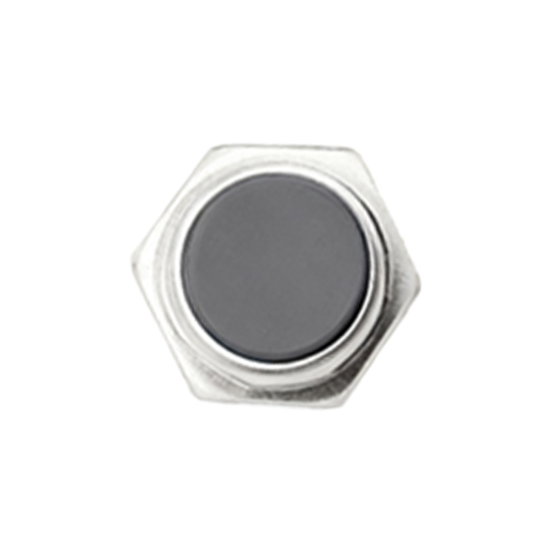
Wiring configurations vary based on the sensor type—sinking (NPN) or sourcing (PNP). For DC two-wire sensors, the sinking type connects the load to the positive voltage supply, with the sensor acting as a switch to ground. In contrast, the sourcing type links the load to ground, with the sensor switching the positive voltage. It is crucial to match the sensor’s polarity with the control system to avoid malfunctions. AC two-wire sensors, often used in mains voltage applications, operate similarly but are designed to handle alternating current, typically ranging from 20V to 250V AC.
Key electrical parameters must be considered during installation. The residual current (leakage current) when the sensor is off can cause unintended activation of sensitive loads. To mitigate this, a bypass resistor or a minimum load current may be required. Additionally, voltage drop across the sensor—usually between 1.5V to 3V—should be accounted for to ensure the load receives adequate voltage. Overcurrent protection, such as fuses or circuit breakers, is recommended to prevent damage from short circuits or excessive inrush currents.
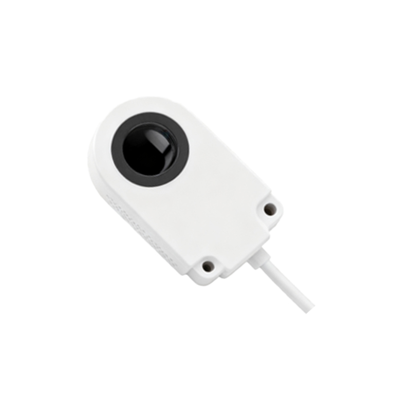
In practical applications, two-wire proximity sensors excel in environments where space and wiring are constrained. Common uses include position detection in conveyor systems, part presence verification in assembly lines, and limit switching in machinery. Their rugged construction allows operation in harsh conditions, with variants offering resistance to moisture, dust, and temperature extremes. However, users should avoid parallel connection of multiple sensors, as this can lead to cross-talk or false triggering. Instead, individual sensors should be wired to separate PLC inputs or relays.
Maintenance and troubleshooting are straightforward. Using a multimeter, technicians can measure voltage across the sensor terminals to verify switching action. If the sensor fails to activate, check for proper voltage supply, correct wiring polarity, and ensure the target material and distance are within specifications. Regular cleaning of the sensing face prevents false readings caused by debris buildup.
In summary, two-wire proximity sensors offer a balance of performance and simplicity. By understanding their wiring principles and adhering to best practices, engineers can optimize their use in diverse industrial settings, enhancing system efficiency and reliability.