In the realm of precision measurement and control systems, laser sensors stand as a cornerstone technology, offering unparalleled accuracy for distance, displacement, and vibration measurements. However, a persistent challenge that engineers and system integrators face is the phenomenon of temperature drift. This technical article delves into the mechanisms of temperature-induced errors in laser sensors, explores their impact on system performance, and outlines practical strategies for mitigation, ensuring reliable operation across varying environmental conditions.
Temperature drift refers to the change in a sensor's output signal that is caused solely by a change in ambient temperature, independent of the actual measured parameter. For laser sensors, particularly those based on triangulation, interferometry, or time-of-flight principles, this drift can manifest as a zero-point shift or a change in sensitivity (scale factor). The root causes are primarily physical, stemming from the thermal expansion and contraction of mechanical components within the sensor housing, such as the lens mounts, internal brackets, and the laser diode casing itself. Even minute dimensional changes can alter the optical path length or the angle of incidence, leading to measurable errors. Furthermore, the electronic components, including the photodetector and signal conditioning circuitry, exhibit temperature-dependent characteristics. The responsivity of the photodiode and the performance of operational amplifiers can vary with temperature, introducing additional noise and offset voltages that corrupt the raw measurement signal.
The consequences of unmitigated temperature drift are significant, especially in high-precision applications like semiconductor manufacturing, metrology, and aerospace assembly. A drift of even a few micrometers over a temperature range of 10°C can lead to out-of-tolerance parts, reduced yield, and compromised product quality. In dynamic control systems, such as active vibration damping, temperature drift can introduce low-frequency errors that degrade system stability and performance.
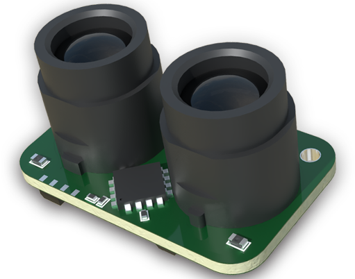
Addressing temperature drift requires a multi-faceted approach, combining sensor design, system integration, and post-processing techniques. At the component level, manufacturers employ several design strategies. The use of materials with low coefficients of thermal expansion (CTE), such as Invar or specialized ceramics, for critical optical and mechanical structures helps minimize dimensional changes. Active temperature control, incorporating thermoelectric coolers (TEC) or heaters with PID control loops, can maintain the core sensor assembly at a constant temperature, albeit at the cost of increased power consumption and complexity. From an electronic standpoint, selecting components with low temperature coefficients and implementing precision, low-drift analog front-end designs are crucial. Some high-end sensors integrate a temperature sensor (e.g., a thermistor or RTD) directly into the optical block. This enables internal compensation algorithms where the microcontroller adjusts the output signal based on a pre-characterized drift model stored in its memory.
For the system engineer, understanding the sensor's specification sheet is paramount. Key parameters to evaluate are the "Zero-point Temperature Coefficient" and the "Sensitivity Temperature Coefficient," typically expressed in units like µm/°C or % of reading/°C. These values define the expected drift over the sensor's operational temperature range. Beyond component selection, effective system integration plays a vital role. Minimizing heat sources near the sensor, ensuring adequate airflow, and using thermally stable mounting structures can reduce the thermal gradient experienced by the sensor. In critical applications, allowing a sufficient warm-up time for the sensor electronics to stabilize is a simple yet often overlooked practice.
For the highest level of accuracy, external compensation methods are highly effective. This involves installing a high-accuracy temperature sensor in close proximity to the laser sensor head and logging temperature data alongside measurement data. In a PC or PLC, a software-based compensation model can then be applied in real-time or post-process. This model is derived from a calibration procedure where the sensor's output is recorded against a known reference at multiple stabilized temperature points within the expected operating range. A polynomial curve is often fitted to this data, creating a correction map that can negate a large portion of the systematic error caused by drift.

In conclusion, temperature drift is an inherent characteristic of laser sensors but not an insurmountable obstacle. A deep understanding of its physical origins allows for informed sensor selection based on application-specific accuracy requirements and environmental conditions. By leveraging advanced design features from manufacturers, implementing sound thermal management in system design, and applying sophisticated calibration and compensation techniques, engineers can significantly suppress the effects of temperature drift. This ensures that laser sensors deliver their promised precision and reliability, forming the bedrock of robust and accurate industrial measurement systems. Continuous advancements in materials science, embedded processing, and calibration methodologies promise even greater resilience against thermal effects in the next generation of laser sensing technology.