In modern industrial automation, laser line tracking sensors have become indispensable components for precision guidance, alignment, and measurement tasks. These sensors project a laser line onto a target surface and use a camera or photodetector array to analyze the reflected pattern. By interpreting deviations in the line's position, shape, or intensity, the system can determine object presence, orientation, edges, or height profiles with high accuracy. This article delves into the core programming principles and code structure necessary to effectively implement these sensors in real-world automation scenarios.
The fundamental operation revolves around image acquisition and processing. Typically, a microcontroller or a dedicated vision processor receives a digital image frame from the sensor's camera. The first step in code is to initialize the communication interface (e.g., UART, Ethernet/IP, or USB) and configure the sensor parameters. This includes setting the laser power, exposure time, frame rate, and region of interest (ROI). A well-chosen ROI reduces processing time by focusing only on the area where the laser line is expected.
A core algorithmic task is line extraction. A simple yet effective method involves scanning each column of the image within the ROI to find the pixel with the highest intensity (the brightest point of the laser line). This creates a set of (x, y) coordinates representing the line's center. For robust performance in varying ambient light conditions, background subtraction is crucial. A common approach is to capture a reference frame with the laser off, store it, and then subtract it from subsequent frames with the laser on. This isolates the laser line signal.
Thresholding is another vital step. The code applies a intensity threshold to distinguish the laser line from noise. Pixels above the threshold are considered part of the line. Adaptive thresholding, which adjusts the threshold based on local image statistics, can handle uneven surface reflectivity. After thresholding, algorithms like a skeletonization or a centroid calculation for each column refine the line to a single-pixel width for precise coordinate generation.
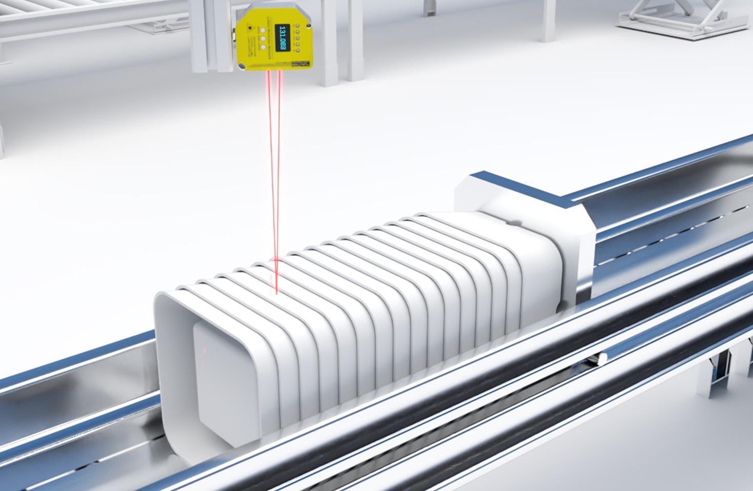
Once the line is extracted, the application logic takes over. For edge detection, the code monitors the x-position of the line's leftmost or rightmost point. A sudden jump indicates an edge. For seam tracking in welding, the code calculates the deviation of the line's center from a predefined reference path and outputs a correction signal. For height profiling, the triangulation principle is used: the y-coordinate of the laser line in the image correlates directly to the distance or height of the target surface. A lookup table or a calibration formula converts pixel displacement to physical units (microns or millimeters).
Error handling and filtering are essential for industrial reliability. The code should include checks for a missing line (e.g., if an object is absent) or a broken line (due to surface gaps). Implementing software filters, such as a moving average or a Kalman filter, on the output coordinates smoothens data and mitigates the impact of transient noise.
Finally, the processed data must be output in a usable format. This could be a simple digital HIGH/LOW signal for object detection, an analog voltage proportional to deviation via a DAC, or a data packet sent over a fieldbus network like PROFINET or EtherCAT to a PLC. The code structure should be modular, separating initialization, image processing, application logic, and communication into distinct functions or classes for maintainability.
Below is a simplified pseudo-code structure illustrating the main loop:
``pseudo
Initialize_Sensor_Communication();
Configure_Parameters(Laser_Power, Exposure, ROI);
Calibrate_Height_Table(); // Optional for profiling
while (System_Running) {
Acquire_Frame();
if (Has_Reference_Frame) {
Frame = Current_Frame - Reference_Frame;
}
Apply_Adaptive_Threshold(Frame);
Extract_Line_Center_Coordinates();
if (Line_Found) {
Apply_Data_Filter();
Calculate_Deviation_or_Height();
Generate_Output_Signal();
} else {
Handle_Error(Missing_Line);
}
Transmit_Data_To_PLC();
}
``
In conclusion, programming laser line tracking sensors involves a blend of low-level hardware interfacing, image processing algorithms, and application-specific logic. A deep understanding of the sensor's optics, the environmental constraints, and the end application is key to writing efficient and robust code that unlocks the full potential of this precise and versatile technology in automated systems.