Reed proximity switch sensors are widely used in industrial automation, security systems, and various electronic applications due to their reliability, simplicity, and cost-effectiveness. Understanding the wiring diagram of a reed proximity switch sensor is crucial for proper installation, operation, and troubleshooting. This guide provides a comprehensive overview of the wiring principles, configurations, and best practices for reed proximity switch sensors.
A reed proximity switch sensor consists of two main components: the reed switch and a magnet. The reed switch is an electrical switch operated by an applied magnetic field. It is typically composed of two ferromagnetic blades (reeds) sealed within a glass tube filled with inert gas. When a magnet approaches the sensor, the reeds are magnetized and attract each other, closing the electrical contacts. Conversely, when the magnet moves away, the reeds separate, opening the circuit. This mechanism allows the sensor to detect the presence or absence of a magnetic object without physical contact.
The wiring diagram for a reed proximity switch sensor generally includes three key elements: power supply connections, load connections, and output signals. Most reed proximity switches are available in two configurations: normally open (NO) and normally closed (NC). In a normally open configuration, the switch contacts remain open when no magnetic field is present and close when a magnet is detected. In a normally closed configuration, the contacts are closed without a magnetic field and open when a magnet is near. The choice between NO and NC depends on the specific application requirements, such as safety considerations or control logic.
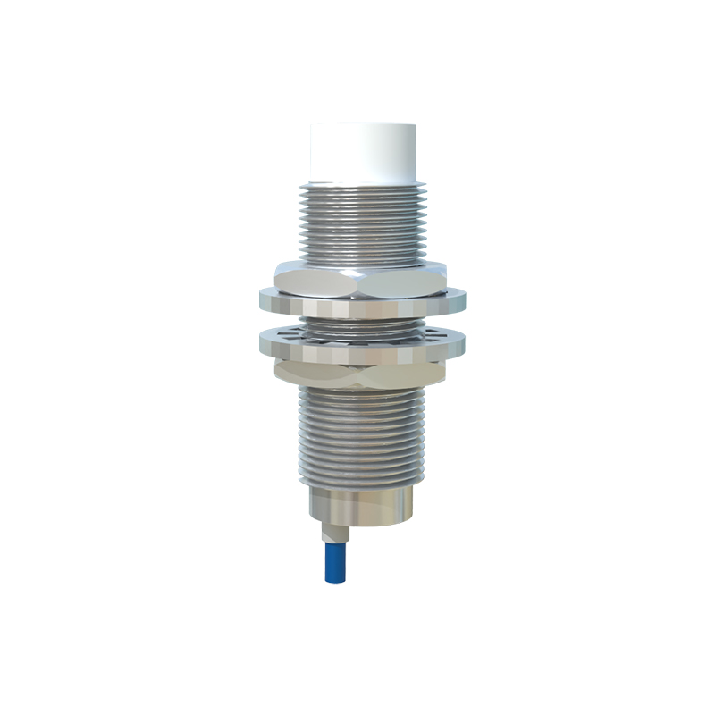
To wire a reed proximity switch sensor, follow these steps based on a typical two-wire DC model:
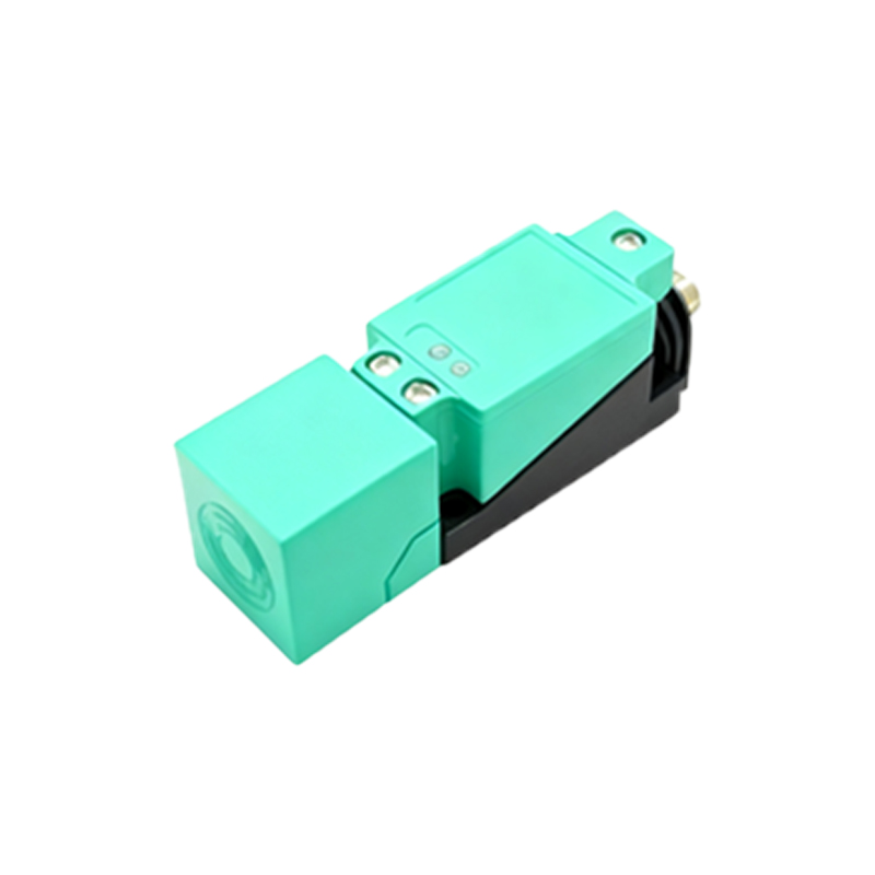
1. Identify the power supply terminals: Connect the positive (+) wire from the DC power source to the positive terminal of the sensor, and the negative (-) wire to the negative terminal. Ensure the voltage matches the sensor's specifications (commonly 5V to 24V DC) to prevent damage.
2. Connect the load: For a normally open sensor, connect one wire of the load (e.g., a relay, PLC input, or indicator light) to the output terminal of the sensor, and the other wire to the negative side of the power supply. When the sensor detects a magnet, the circuit closes, allowing current to flow through the load. For a normally closed sensor, the wiring is similar, but the load is activated when no magnet is present.
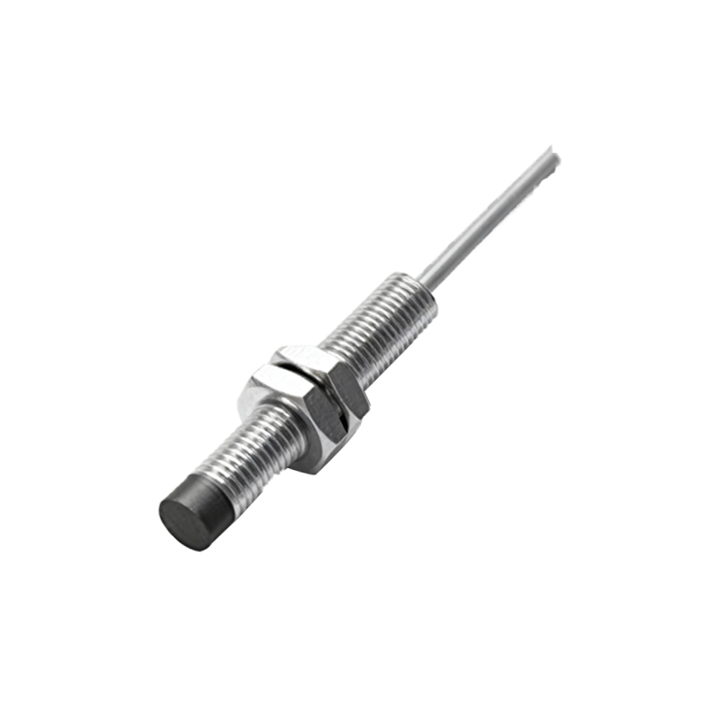
3. Verify grounding and shielding: In environments with electrical noise or interference, use shielded cables and proper grounding techniques to ensure stable operation. Connect the shield to ground at one end to avoid ground loops.
For three-wire reed proximity switches, which are common in industrial settings, the wiring diagram includes separate wires for power, ground, and output. The brown wire is typically for positive DC voltage, the blue wire for negative or ground, and the black wire for the output signal. This configuration allows for easier integration with programmable logic controllers (PLCs) and other control systems. Always refer to the manufacturer's datasheet for specific wire colors and terminal designations, as they can vary by brand and model.
When installing reed proximity switch sensors, consider the following tips:
- Mount the sensor securely to avoid vibration or movement that could affect detection accuracy.
- Maintain an appropriate gap between the sensor and the magnet, usually specified by the manufacturer (e.g., 5mm to 10mm). Excessive distance may cause unreliable switching.
- Avoid placing the sensor near strong magnetic fields or ferrous materials that could interfere with its operation.
- Use appropriate wire gauges and connectors to handle the current and voltage requirements of the application.
Troubleshooting common issues with reed proximity switch sensors often involves checking the wiring connections. If the sensor fails to activate, verify that the power supply is functioning and the voltage is correct. Inspect for loose or corroded wires, and ensure the magnet is within the detection range. For false triggers, check for environmental interference or misalignment between the sensor and magnet. In cases of persistent problems, consult the sensor's manual or replace the unit if damaged.
Reed proximity switch sensors are versatile devices suitable for applications such as door and window sensors in security systems, position detection in machinery, and liquid level sensing in tanks. Their non-contact nature makes them ideal for harsh environments where dirt, moisture, or wear could affect mechanical switches. By mastering the wiring diagram and following best practices, engineers and technicians can ensure reliable performance and longevity of these sensors in various industrial and commercial setups.
In summary, the wiring diagram for a reed proximity switch sensor is straightforward but requires attention to detail for optimal results. Whether using a two-wire or three-wire configuration, proper connection to power, load, and output terminals is essential. Adhering to installation guidelines and troubleshooting steps will help maximize efficiency and minimize downtime in automated systems.
SEO关键词